Week - 4 - 2D meshing for Plastic components
Aim:
The objective of the project is to perform preprocessing i.e. geometry cleanup, mid surface extraction, and 2D shell meshing for the plastic bottle cap. After meshing, component thickness and material need to be assigned to the mesh. And the mesh should follow the following quality criteria.
|
S.No |
Quality Criteria |
Value |
|
1 |
Target/Average length |
1 |
|
2 |
Minimum Length |
0.5 |
|
3 |
Maximum Length |
3 |
|
4 |
Aspect |
3 |
|
5 |
Warpage |
15 |
|
6 |
Skewness |
45 |
|
7 |
Jacobian |
0.7 |
|
8 |
Minimum Quad Angle |
45 |
|
9 |
Maximum Quad Angle |
135 |
|
10 |
Minimum Tria Angle |
30 |
|
11 |
Maximum Tria Angle |
120 |
|
10 |
Tria Percentage |
15 |
Procedure:
The plastic bottle cap model is imported into the ANSA.
After importing the model we should properly analyse and understand the geometry. When a CAD model is imported into the ANSA, there might be several geometrical errors like missing/distorted surfaces, intersecting surfaces, etc. due to format conversion.
To ensure that all the surfaces are connected properly Faces>Topo tool is used for all the edges of each individual component at a time.
Next, geometry check is performedf by going to Checks>Geometry and running it for parameters as shown below.
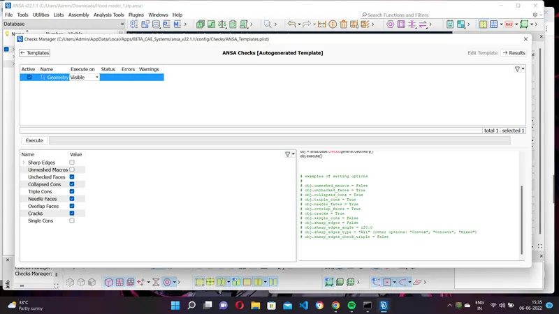
Most of the errors were fixed automatically by right clicking on the error and clicking fix. Next the orientation of all the faces is modified by going to Faces>Orient. This ensures that all faces are oriented similarly.
The Faces>Middle option is used is certain areas to extract the midsurface.
The midsurface is extracted using Faces>Offset and selecting all the surfaces on one face. Then half of the thickness value is given as the offset value.
Since they are sheet metal components the thickness is uniform across the component. Then, four properties are created and assigned to the components using Set PID and Properties>New. Thickness is assigned to each properly and material.
Next mesh parameters are configured by Utilities>Mesh Parameters.
Next quality criteria is configured by using Utilities>Quality Criteria.
Since the outer and inner extract are symmetrical one half of the symmetry is taken for meshing.
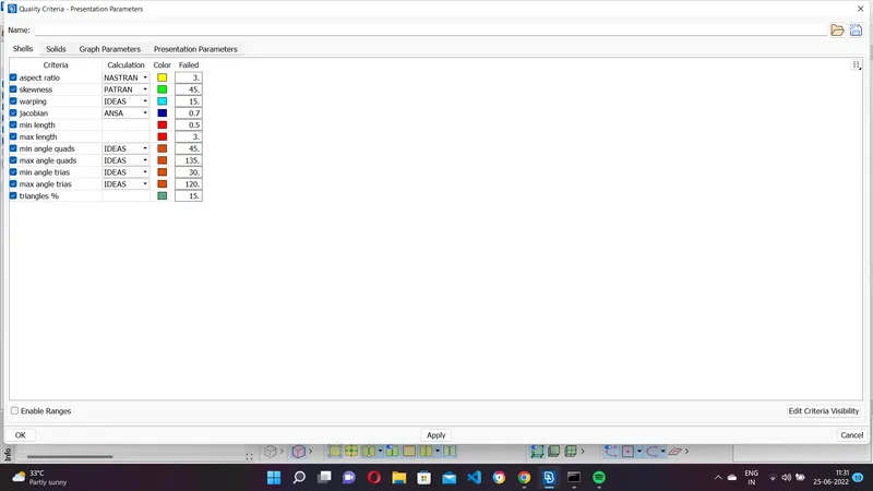
The next step is meshing. Before that we should switch to the mesh module. First the shell element length is altered using Perimeters>Length and all the CONS are selected and target element length 5 is fed as length value.
Each face of each component is meshed using the Best option in the Mesh Generation.
Mesh quality is improved using reconstruct option in Shell mesh.
Further failed elements and trias are rmoved using Swap, Split, Join, Smooth, Paste and Num+/-

Finally the shell element representation is changed by using Utilities>Quality Criteria>Presentation parameters and enabling the 'Draw shell as solid'.