Week - 4
Aim = Create a Simulink model using Stateflow in the Simulink environment.
Objective = a. Implement control logic of a “washing machine” using Stateflow.
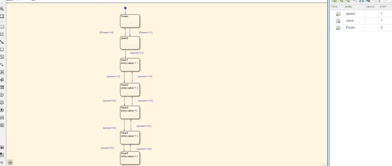
b. Create a Simulink chart for the “Gear shift” logic.
Observation=
a. washing machine
1. system running time is 400 sec
2. power and speed are provided as input, and power control is done by using 'Rocker switch'.
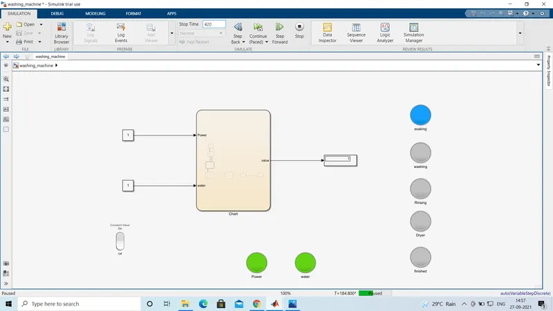
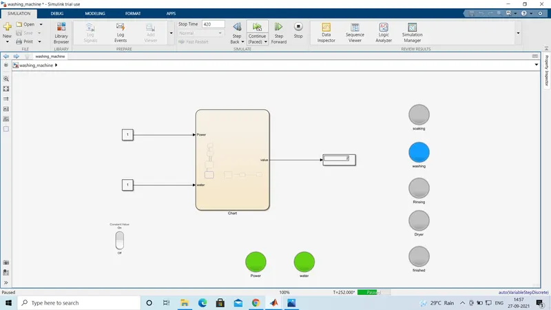
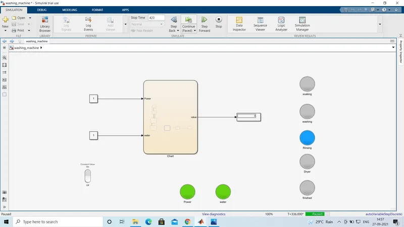
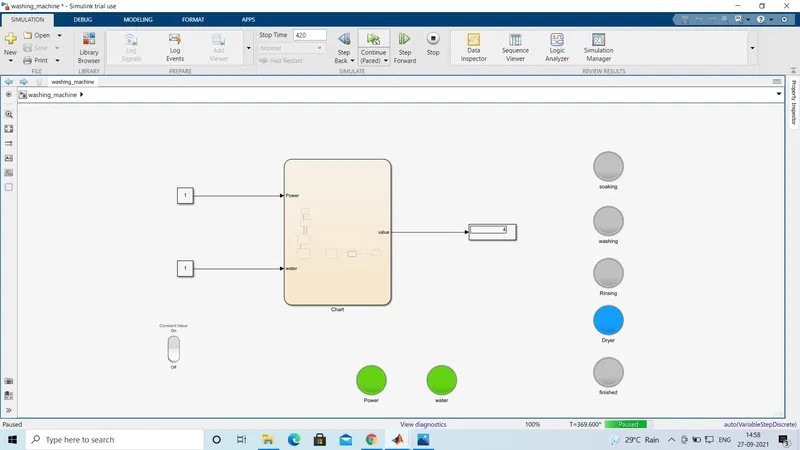
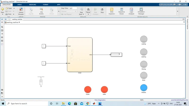
3. output is connected to scope and lamps are also used, Each lamp will glow up according to washing machine process.
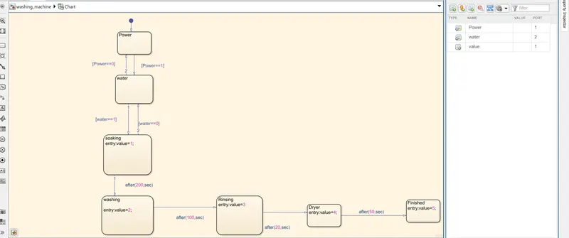
4. we use chart command for washing machine process
5. In that chart power and water are provided as input for the following process, if water is not available(water==0) then the system will stop
6. The soaking process will be done for 200 seconds during this process 1 will be shown on the display and the soaking lamp will only glow for a given time of soaking after that it will stop glowing.
7. The Washing process will be done for 100 seconds during this process 2 will be shown on the display and the washing lamp will only glow for a given time of washing after that it will stop glowing.
8. The Rinsing process will be done for 20 seconds during this process 3 will be shown on the display and the rinsing lamp will only glow for a given time of rinsing after that it will stop glowing.
9. The Dryer process will be done for 50 seconds during this process 4 will be shown on the display and the dryer lamp will only glow for a given time of dryer after that it will stop glowing.
10. after this process System will stop .finished lamp will glow to show the process is finished and the power and water lamp will turn red.
a. Chart of a washing machine process
b. Soaking
c. Washing
d. Rinsing
e. Dryer
f. finished
B. Gear shift
1. System running time is 80 sec
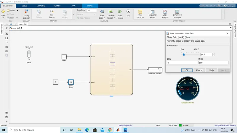
2. power and speed are provided as input and for speed we use the 'slider gain' block ( In this block we can also change the value during the process).
3. output connected to display (Gear shift Indicator) to show the gear shifting.
4. rocker switch is connected to power and a circular gauge is used to show the change in speed during the process.
a. Chart of Gear shift
b. 1st Gear
b. 2nd gear
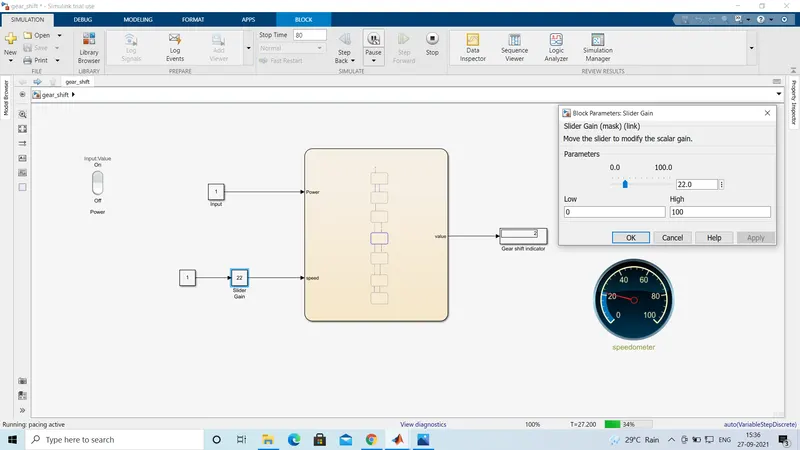
c. 3rd gear
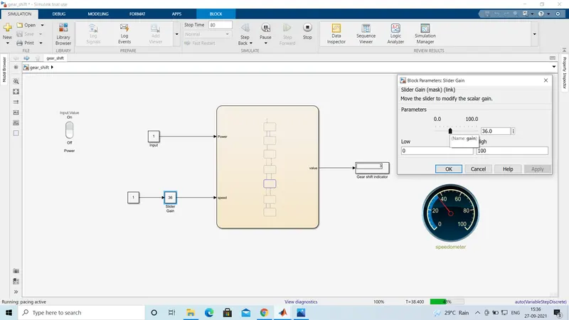
d. 4th gear
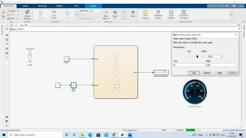
5. 5th gear
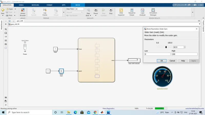
Conclusion= with help of the chart command in Simulink I was able to create a control logic of washing machine and gear shift.