Week - 4
CONTROL LOGIC OF A WASHING MACHINE
A washing machine can be imagined as a Finite State Machine where, depending upon its modes(s) of operation and certain conditions, it can be classified to be in one of a finite set of states at any given time.
A modern, regular washing machine generally performs 4 distinct operations, viz.
- SOAKING
- WASHING
- RINSING
- DRYING
These four operations are carried out in the sequence that they have been put in the list above. Out of these, the first three operations require water supply and the remaining one, i.e., DRYING, as its name suggests, is simply drying the wet clothes for which water supply is not necessary.
After performing these four operations, the wash cycle comes to an end, which is to say that the machine has "finished" its job.
As in the case of all electrically driven machines, a washing machine cannot run without a power supply. Hence, when electrical power is not supplied to it, the machine is considered to be in an "OFF" state.
Water supply is an important factor in washing machine operation. The machine will carry out the wash cycle successfully if it has water supply as when required (SOAKING, WASHING and RINSING operations). If not, then the machine either does not even enter the ON state from OFF state if the water supply is absent from the very beginning, or, if the water supply somehow ceases while in any of the three operating modes of SOAKING, DRYING and RINSING, the machine stops its operation.
From the information provided above, the machine can be said to have altogether 7 distinct states. These states are nothing but the different 'modes' the machine can be in at any given time. These states are as follows:
- OFF state
- SOAKING state
- WASHING state
- RINSING state
- DRYING state
- FINISHED state (upon successful completion of a wash cycle)
- STOP state (when water supply ceases during wash cycle)
States (ii) to (vii) can be cumulatively considered as ON state.
According to the problem statement provided in the question, following are the time durations during which the each of the 4 operating modes are active:
SOAKING : 200 seconds
WASHING : 100 seconds
RINSING : 20 seconds
DRYER : 10 seconds
Each ON-state has an associated LED that stays 'on' for the entire duration of that state being active and turns 'off' as soon as the state is exited.
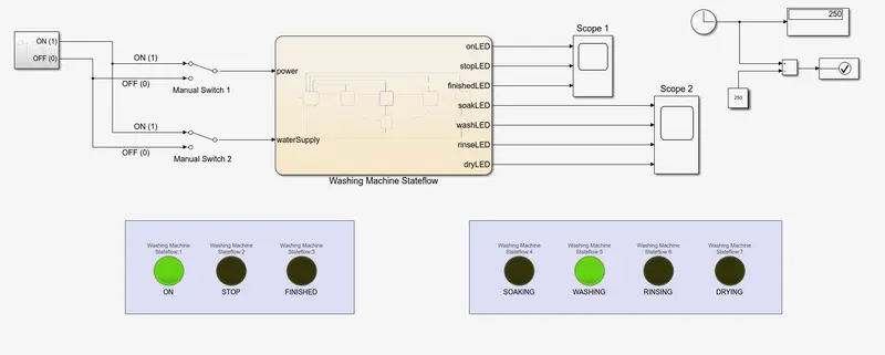
The simulink model of the aforementioned system is shown in the pictures below.
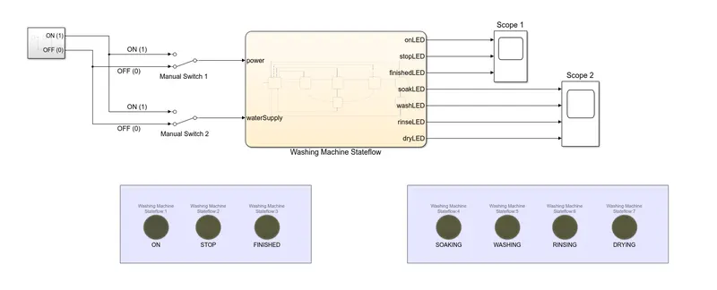
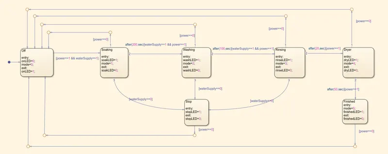
Power and Water Supply are the two inputs to the system. The outputs are 7 LED signals which indicate the operation and activity of the machine. The OFF state is the default state. Both power and water supply are required to exit OFF state and enter ON state. Loss of power supply anytime during ON state will result in machine transitioning to OFF state.
The model is simulated for certain test cases.
- Case 1 : Both Power and Water Supply are OFF (0)
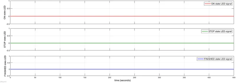
The resulting LED output signals as viewed in the two scopes are shown below.
SCOPE 1:
SCOPE 2:
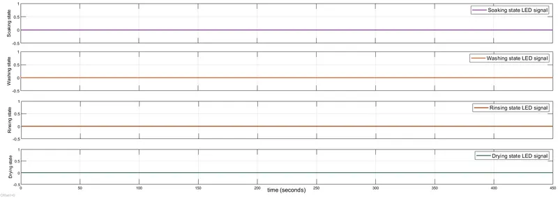
Clearly, with both the supplies being off, the model remains in OFF state and does not enter into any other state for the entirety of the simulation (ON state = 0 means OFF state = 1, as `ON = bar{OFF}`).
All of the LED lamps on screen stay inactive.
- Case 2 : Both Power and Water Supply are ON (1)
The resulting LED output signals viewed in the two scopes are shown below.
SCOPE 1:
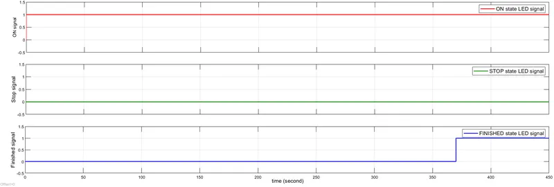
SCOPE 2:
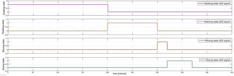
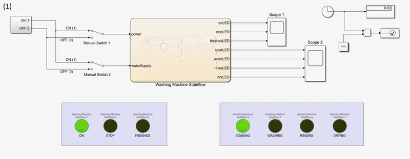
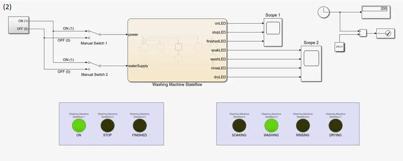
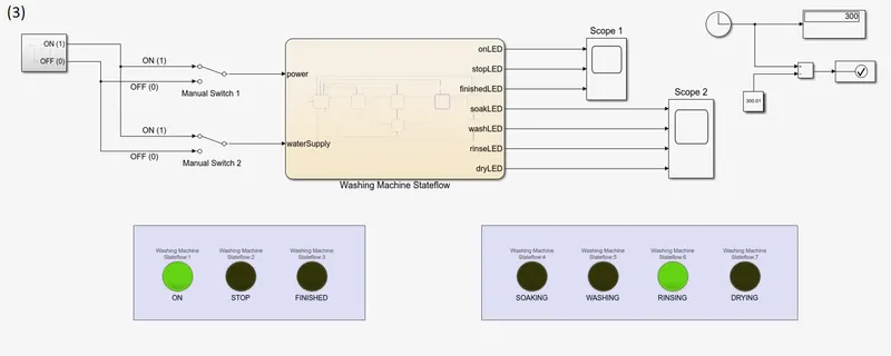
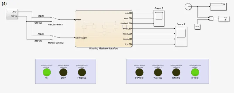
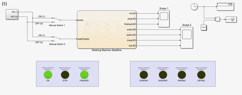
Throughout the simulation, Power and Water Supply are available (i.e. value = 1). Hence. Washing Machine successfully completes its wash cycle. The machine enters the ON state as soon as the first time step elapses and SOAKING state becomes active. 200 seconds after that, state transitions from SOAKING to WASHING (`t = 200 sec`). After 100 seconds of being in that state, the third transition occurs. Active state is now RINSING (`t = 300 sec`). 20 seconds after that, fourth transition takes place from RINSING to DRYING (`t = 320 sec`). System remains in DRYING state for 50 seconds before transitioning to FINISHED state (`t = 370 sec`). Post this, system remains in this state indefinitely until the power supply is disconnected (value = 0). This process is further demonstrated by the following images showing the active LED lamps w.r.t. time.
- Case 3 : Water Supply is turned off mid-process
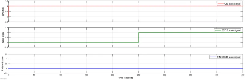
The Water Supply signal is turned off at `t = 250 sec`, during the WASHING state. The resulting LED output signals as viewed in the scope are laid down below.
SCOPE 1
SCOPE 2
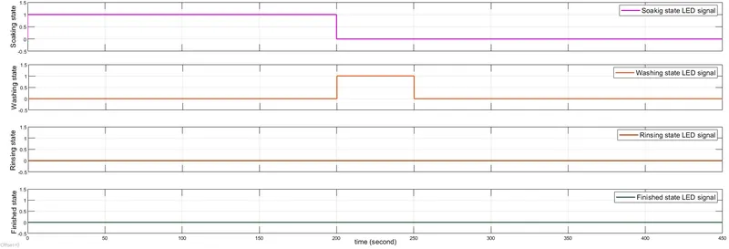
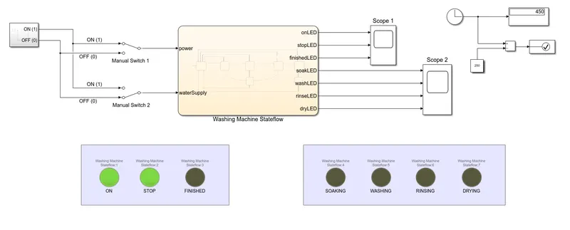
The Water Supply is cut off at `t = 250 sec`. Prior to that, system was in its normal wash cycle: turning ON, completeing SOAKING and then moving into WASHING. Mid-way during this state, with ceasing of Water Supply, wash cycle gets hindered and machine transitions into STOP state. The following images capture this phenomenon through shining of LED lamps.
(1) Just immediately prior to Water Supply being stopped
(2) The end of simulation with Water Supply cut off at t = 250 sec
From the discussion above, it becomes clear that the washing machine does run according to the logic requirement as mentioned in the problem statement.
GEAR SHIFT LOGIC
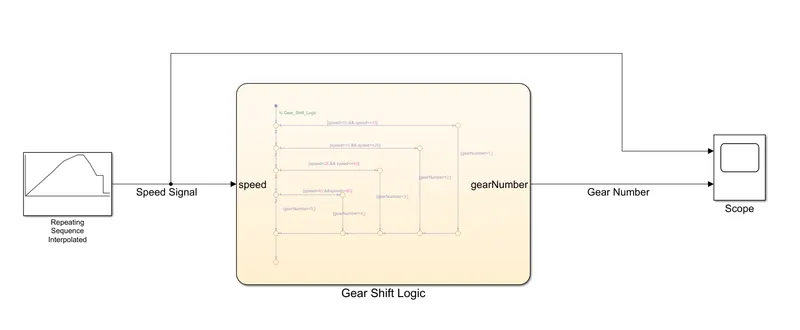
In this problem, the vehicle's speed is taken as an input to the state chart and the gear number is output based on the logic mentioned.
The logic has been implemented in the form of if-else construct provided by stateflow environment.
The model pictures are provided below.
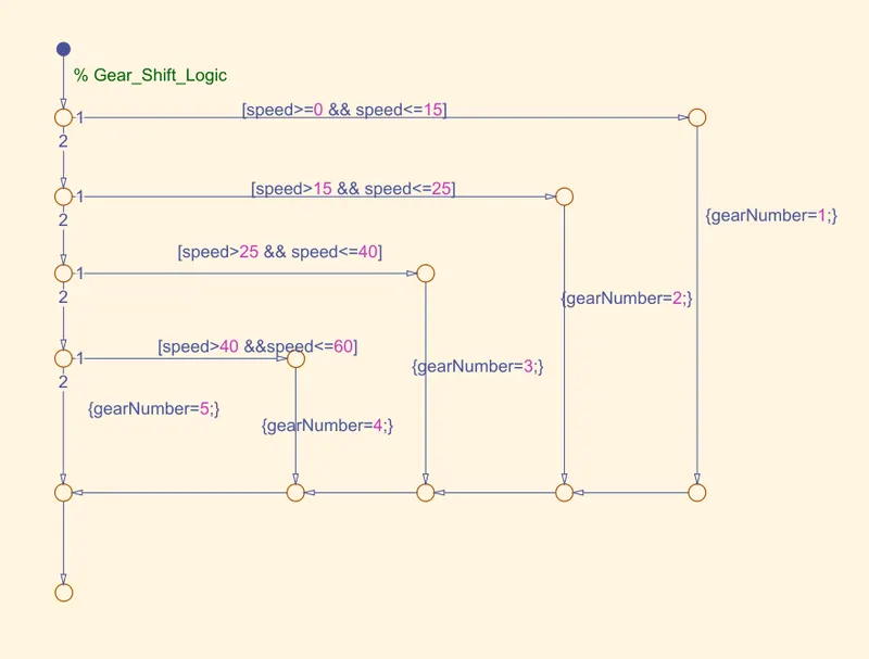
The equivalent Java code snippet is as follows:
double speed;    //Positive Real Number
int gearNumber;  //Positive Integer

if(speed>=0 && speed<=15)
{gearNumber=1;}
else if(speed>15 && speed<=25)
{gearNumber=2;}
else if(speed>25 && speed<=40)
{gearNumber=3;}
else if(speed>40 && speed<=60)
{gearNumber=4;}
else
{gearNumber=5;}
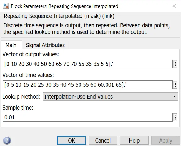
A Repeating Sequence Interpolation block has been used to generate the speed signal. It is shown in the image below.
The model was simulated for 65 seconds. The speed and gear number plots were captured in Scope and have been shown in the image below.
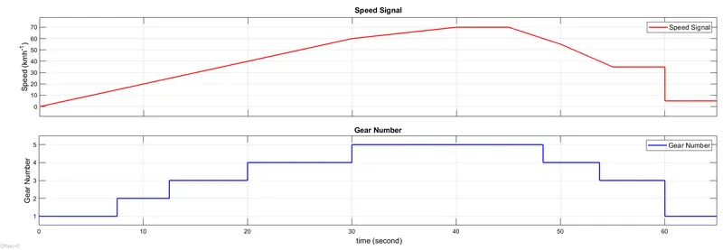
From the figure, it can be concluded that the gear shift happens exactly in accordance to the problem statement. Hence, the validity of the logic of the stateflow is verified.