Week -2
1. SIMULINK MODEL OF DOORBELL USING SOLENOID BLOCK
The schematic diagram of the doorbell system is shown in the following image
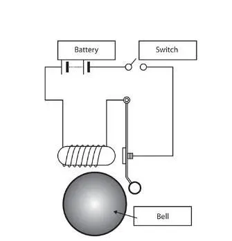
The battery is used to power a solenoid, which develops a magnetic field. The magnetic field attracts the metal plunger (which here is the metal arm) with a force and causes the bell to ring when the arm strikes it. A switch is placed the electrical circuit to control powering of the solenoid, thus giving control over the bell's ringing.
The Simulink model of the aforementioned system has been laid out in the figure below:
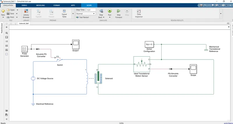
The DC voltage source powers the solenoid through a switch, which is controlled by a pulse generator having a period of 4 seconds and On-time of 2 seconds. The position of the plunger is tracked through an Ideal Translational Motion Sensor and the output is captured in a scope. Model is simulated for 12 seconds, thus completing three periods.
In the solenoid block, the spring constant has been set to 50 N/m ; remaining parameters have been kept at their default values.
The plunger(i.e. bell arm) position with respect to time and the pulse generator signal are shown in the figures below:
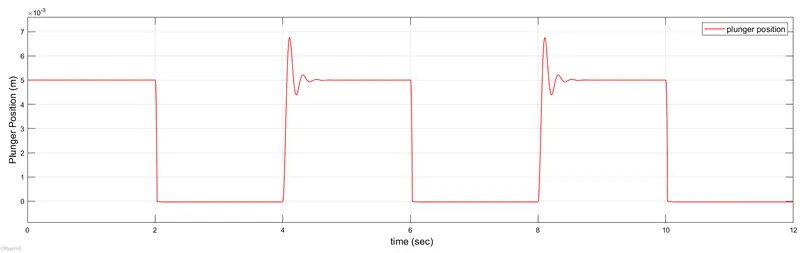
Figure: Plunger position
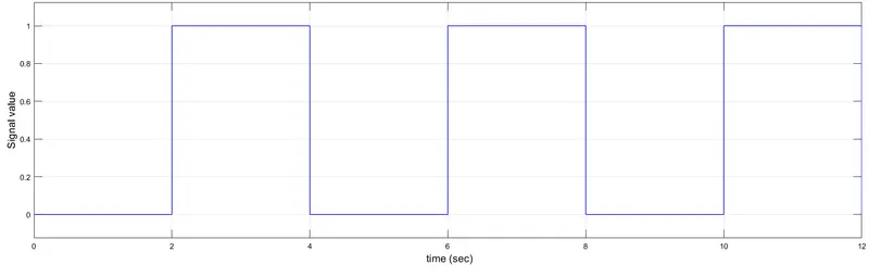
Figure: Signal Generator output
From the two figures, it can be seen that when switch is OFF (Signal value = 0), the plunger is at its original position (5mm air gap) . As soon the switch is turned ON (Signal Value = 1), the plunger is pulled by the solenoid (0mm air gap). Again, when the switch is turned OFF from ON, the solenoid loses power and the plunger's spring pulls it back to its original position. At this stage, oscillations in the pulnger position is noticed before coming back to steady state position of 5mm. This is due to the fact that the inertia of the plunger does not allow it to come to rest immediately and the spring + damping slowly brings it down to the initial position.
2. THERMISTOR REGULATED TEMPERATURE SENSOR
A thermistor is a semiconductor device which changes its resistance depending on temperature. It was invented by Faraday in 1833. There are two types of thermistors available, viz, NTC (Negative Temperature Coefficient) and PTC (Positive Temperature Coefficient) thermistors. In NTC thermistors, the resistance reduces as the temperature rises and vice versa. In PTC thermistors, the exact opposite happens.
The mathematical relationship between temperature and resistance in thermistor used is laid out below:
R(T) = R0`times``e^(B(1/T - 1/T_0)`
Here, R0 is the base value of resistance at temperature T=T0. B is the characteristic temperature constant.
A thermistor placed in series with a voltage source and a constant resistance will vary the current flowing in the circuit, causing the voltage drop across the constant resistance to vary accordingly. The model of the system is shown in the figure below:
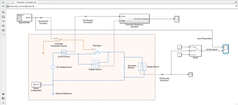
- In the figure, a DC voltage source (value = 10 volts in this model) is connected is series with the thermistor, along with a fixed resistor named 'Secondary Resistor' (value = 10 ohms in this model). A voltage sensor senses the voltage drop across the 'Secondary Resistor'.
- The thermistor is connected to a Controlled Temperature Source, to which the signal builder supplies the temperature values in accordance to the problem statement.
- The 'Secondary Resistor' voltage values are utilised to trigger the switch, where if the voltage signal exceeds a certain threshold value, the switch is ON and OFF otherwise.
Thermistor specifications:
Type: NTC
Nominal Resistance, R0 = 1000 `Omega`
Characteristic Temperature Constant, B = 3500 K
Nominal Temperature, T0 = 298.15 K
Thermal time constant = 5 seconds
Dissipation factor, K_d= 0.75`times``10^-3`
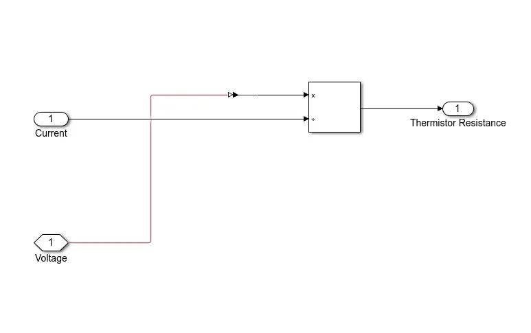
A volatge sensor connected across Thermistor, named 'Voltage Sensor1' measures the voltage drop across the thermistor. The current sensor measures the circuit current. Their readings have been utilised to calculate the resistance of the thermistor in the subsystem 'Thermistor Resistance Calculator', using Ohm's law. The subsystem has been shown in the following image:
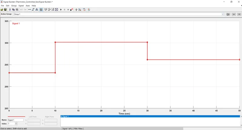
The signal builder supllies temperature values as follows:
- 293.15K , 0`<=`t`<=`10
- 300.15K , 10`<=`t`<=`30
- 296.15K , 30`<=`t`<=`50
where t is time is seconds. The image of the same has been shown below:
The model was simulated for t=50 seconds.
The thermistor resistance profile is shown in the image below:
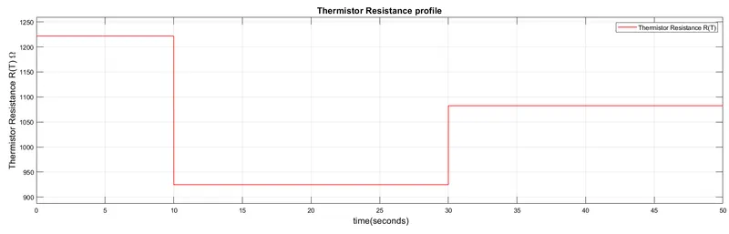
As is the case in NTC types, an increase in temperature causes resistance to decrease and vice versa and can be seen by comparing the input temperature data and thermistor resistance profile.
The voltage sensor output (across 'Secondary Resistance') is shown below:
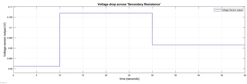
When temperature is 27 degree Celcius, the voltage drop is highest. According to the question, the switch must turn ON when temperature is above 20 degrees. Hence, from 10s to 30s, the switch must turn ON and remain OFF otherwise. The voltage sensor output is fed to the control port o the switch and threshold has been set to 0.1, as only when temperature crosses 25 degrees that this value is reached/crossed in our case. Port1 is fed a condtant valueof 1 and port3 an constant value of 0. As soon as voltage sensor output crosses the threshold, output port transmits port1 signal of value 1 (SWITCH -> ON) and otherwise, it transmits port3 signal of value 0 (SWITCH -> OFF). This behaviour is captured in the following figure:
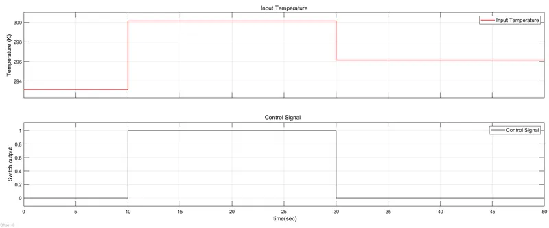
From the figure, it is clear that switch activates only when time t`in`[10s, 30s].
CONCLUSION
The thermistor captures changes in temperature through variation of its resistance, which is reflected in the associated series resistor's voltage drop. This voltage drop is then utilised to operate the switch in accordance to the problem statement, where it activates ony when and during temperature is above 25 degrees celcius and remains OFF otherwise, which is in accordance to the problem requirement.