Week - 4
Aim: Implement control logic of a washing machine using stateflow as per given sequence
- if the power supply is available, the system gets activated.
- if the water supply is not available, stop the process and indicate through LED
- soaking time should be 20s followed by washing time of 100s
- then rising happens for next 20S and dryer runs for 50s.
after all the process have completed turn on finished LED
2. Make a simulink chart for the gear shift logic as per below conditions;
Speed Range (kmph) Gear
0 to 15 1
16 to 25 2
26 to 40 3
41 to 60 4
above 61 5
give spped input while the simulation is running and display the gear number.
Procedure
working principle of a washing Machine
A washing machine by spinning at 800 to 1600 rpm helps soap and dirt with it to leave the surface of the cloth via centrifugal force and into outlet pipes hence utilizing centrifugation to both clean and partially dry the clothes loaded in it. Thus the process are electrically controled, such as the drum, valves, pump, motor and heating. The valve opens again and the dirty water drains out of the drums. the pump works to help get rid of the water. The valve lets clean water in again into the drums.
Model With Working Machine:
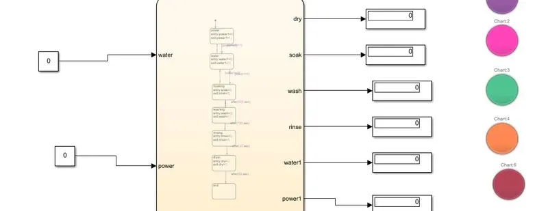
Model with State_flow
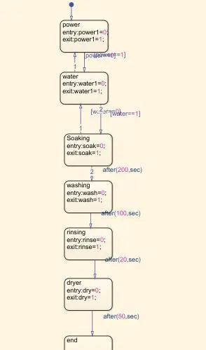
Explanation:
1. For making the model, we have to create a stateflow chart with power, water, soak, time, washing time, Rinising, dry and end of the cycle.
2. To start with the charts we require a breakpoint added with chart power.
3. From the power to water we make a loop with conditions if power is one the flow of current goes to engage the water and when the water has one condition the washing machine cycle runs from soak till the end.
4. Flow chart notation use connective junctions to represent common code structures like loops and constucts without use of states.
5. i have given soak time entry A=0 and Exit A=1 with this we set breakpoint flow of water is for 200 seconds and once it reaches above 200 seconds it will go to next process washing. the washing rinising and dry set as per given time.
6.here i have input end=1 so the lamp will indicate when display is 1
7.after creating the charts we have to check the input and output through the symbols tool which is visible on the left side of the chart page, in the type column, we have to define the the input and output.
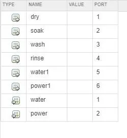
after giving the input and output like water and power from the input and the result will be display through the 0 and 1
once the model run for 220 seconds, the different result can be displayed in various conditions.
Results:
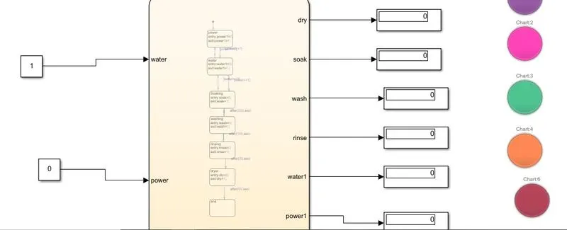
1.When the input both water and power will be OFF(0)
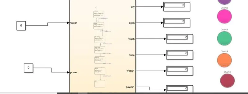
Power OFF and Water Supply ON
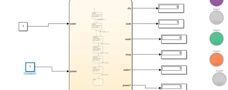
Both Power and Water Supply is ON
Gear Shift:
A manual transmission as gearbox, a type of transmission used in motor vehicle applications. it uses a driver operated clutch usually engaged and disengaged by a foot pedal or hand lever, for regulating torque transfer from the engine to the transmission and gear selector can be opeared by hand.
Simulink Model
in this model inputs are generated to slider gain which is connected to constant block the valve is 1. The gear shift is acted by conditions in stateflow.
2. the gear is shifted at various speed
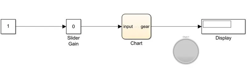
Stateflow model of varing gear box

The different gear speed is as assigned as shown below
gear speed display_gear
1 0 1
2 15 2
3 25 3
4 40 4
5 60 5
By giving the input slider gain such as 0 15 25 40 and 60 , the display output give accordingly as 1 2 3 4 and 5 respectly accord to speed of the gear as shown below
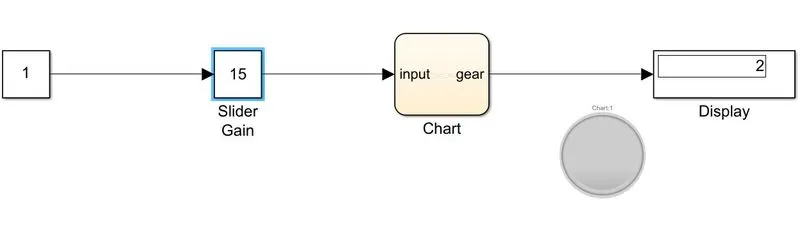
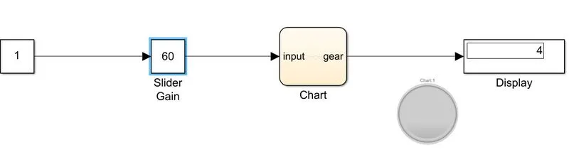
so finally according to speed variation automatically gear also chaning with input condition shown .