Week - 4
2. Make a Simulink chart for the “Gear shift” logic as per below conditions:
Speed Range(kmph) Gear
0 to 15 1
16 to 25 2
26 to 40 3
41 to 60 4
Above 61 5
Give speed input while the simulation is running & display the gear number.
Part 2
Implementing of control logic for gear shift using the state flow.
1.start simulink and create a blank model
2.search for CHART block in the stateflow category of library browser.
3.open the chart block and select the various features from the stateflow window.
4.control logic for gear shift is such that it should change the gear when the speed increases of decreases automatically.
5.after finishing the control logic run the stateflow and check the gear shift operation foe an infinite time.
BLOCK USED:
1.CHART
a finite state machine is a representation of an event-driven(reactive)system.in a event-driven.the system responds to an event by making a transtion.
2.DISPLAY
the display block shows the value of the input data.you can specify the frequency of the display.for numeric input data.you can also specify the format of the display.
3.CONSTANT
in the constant block we will give the speed range.
LOGIC:
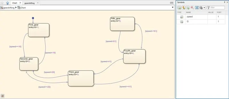
SIMULINK MODEL:
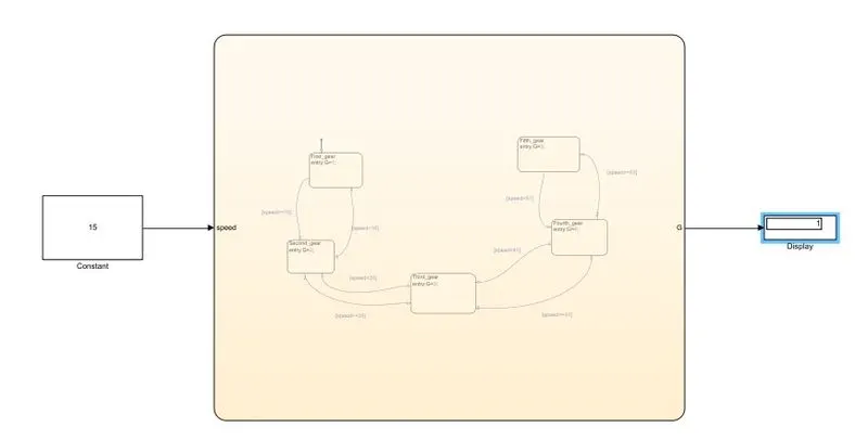
when you give the speed range between 0 to 15 in display block it will show the gear.
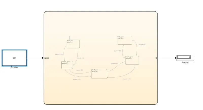
when you give the speed range between 16 to 25 in display block it will show the gear.
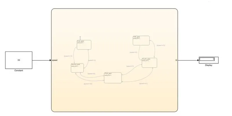
when you give the speed range between 26 to 40 in display block it will show the gear.
when you give the speed range between 41 to 60 in display block it will show the gear.
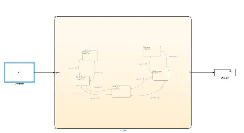
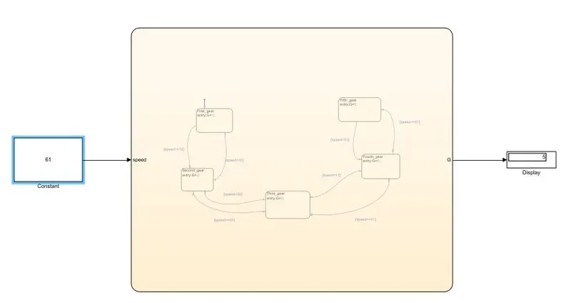
when you give the speed range above 61 in display block it will show the gear.
- Implement control logic of a “washing machine” using Stateflow as per given sequence:
- If the power supply is available, the system gets activated
- If the Water supply is not available, stop the process & indicate through LED
- Soaking time should be 200s followed by Washing time of 100s.
- Then rinsing happens for next 20s & dryer runs for 50s
Part 1
Implementing of control logic for washing machine using the state flow.
1.start simulink and create a blank model
2.search for CHART block in the stateflow category of library browser.
3.open the chart block and select the various features from the stateflow window.
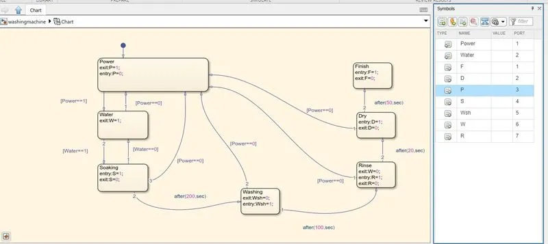
4.control logic for washing m\c is such that it should soak the water for the first 200 sec followed by washing time 100sec.rinsing the water for the thext
20sec followed by drying time 50sec.
5.after finishing the control logic run the stateflow and check the sequence of the operation for 370sec.
BLOCK USED:
1.CHART
a finite state machine is a representation of an event-driven(reactive)system.in a event-driven.the system responds to an event by making a transtion.
2.DISPLAY
the display block shows the value of the input data.you can specify the frequency of the display.for numeric input data.you can also specify the format of the display.
3.constant
we have connected two constant block one is power and another is water.use this block to provide a constant signal input.
4.lamp
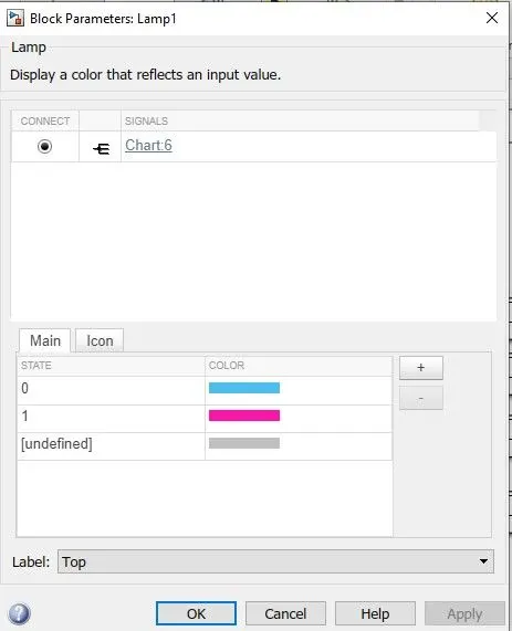
the lamp block will display the color indicating the value of the input signal.you can use the lamp block with other dashboard blocks to build an interactive.
WASHING MACHINE LOGIC:
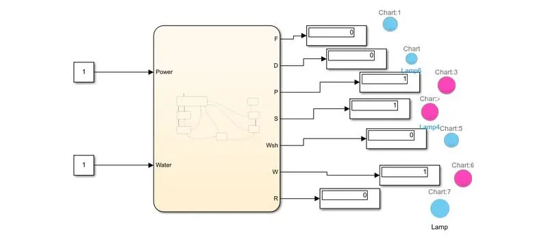
TIME AT 200SEC:
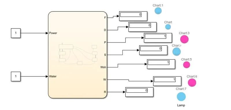
TIME AT 250SEC:
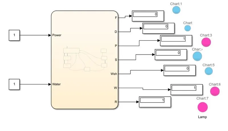
TIME AT 320SEC:
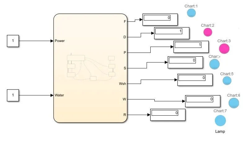
TIME AT 340SEC:
TIME AT 400SEC AT COMPLETE STAGE:
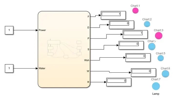
HERE BLUE LIGHT MEANSS OPERATION IS NOT COMPLETED AND RED LIGHT LIGHT SHOWS OPERATION IS COMPLETED.WHICH IS ALSO CHECK FROM DISPLAY BOX AS OUTPUT 1.