Week 4.2: Project - Transient simulation of flow over a throttle body
JORGE LOZANO
Advanced CFD for IC Engine Applications using Converge
Project - Transient simulation of flow over a throttle body
Objective
- Setup and run transient state simulation for flow over a throttle body.
- Post process the results and show pressure and velocity contours.
- Show the mesh (i.e surface with edges)
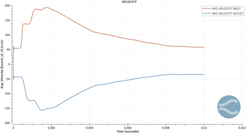
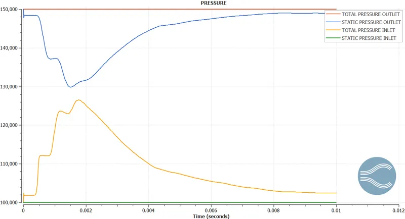
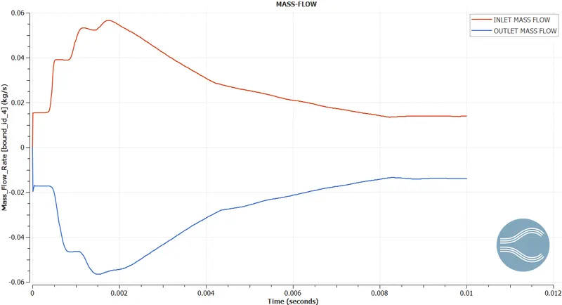
- Show the plots for pressure, velocity, mass flow rate and total cell count.
- Also show the calculations on how you calculated an end time for the simulation.
- Create an animation in which it throttle movement should be visible.
RNG K-E TURBULENCE MODEL
k-e turbulence modelling [1]
by Yakhot et al to renormalize the Navier-Stokes’s equations, to account for the effects of smaller scales of motion. In the standard k-epsilon model the eddy viscosity is determined from a single turbulence length scale, so the calculated turbulent diffusion is that which occurs only at the specified scale, whereas all scales of motion will contribute to the turbulent diffusion. The RNG approach, which is a mathematical technique that can be used to derive a turbulence model like the k-epsilon, results in a modified form of the epsilon equation which attempts to account for the different scales of motion through changes to the production term.
Application: Although the technique for deriving the RNG equations was quite revolutionary at the time, it's use has been lower key. Some workers claim it offers improved accuracy in rotating flows, although there are mixed results in this regard: It has shown improved results for modelling rotating cavities but shown no improvements over the standard model for predicting vortex evolution (both these examples from individual experience). It is favored for indoor air simulations.
Pre-processor
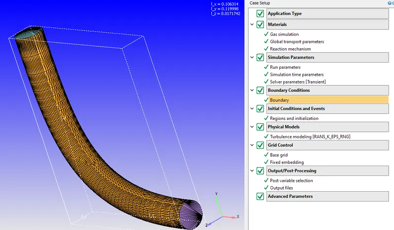
The following transient simulation will be in the software converge Studio, performing a ho hydrodynamic test simulation seeing the rotation of the throttle throughout the complete time, and a complete hydrodynamic simulation applying the Navier stokes equations.
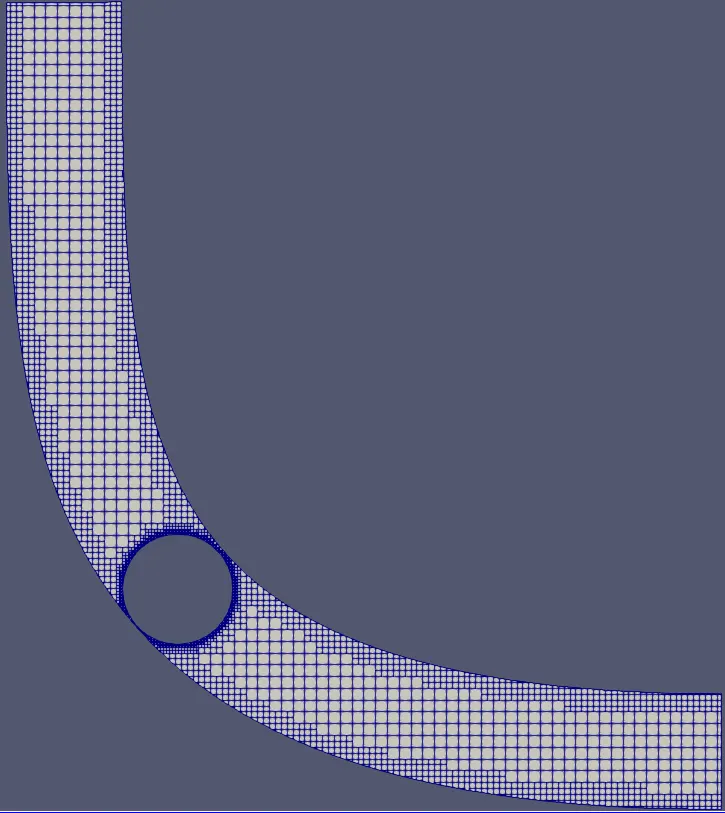
Every 0.002 second, 20 degrees will rotate up to 0.008 and 80 degrees, having embedding mesh refinement on the throttle for 3 levels on the throttle walls and 2 on the exterior walls. Having an inlet outlet pressure difference and applying the law of the wall with a turbulence RNG K-E model
Geometry & Case Setup
Postprocessing
Transient case
Paraview
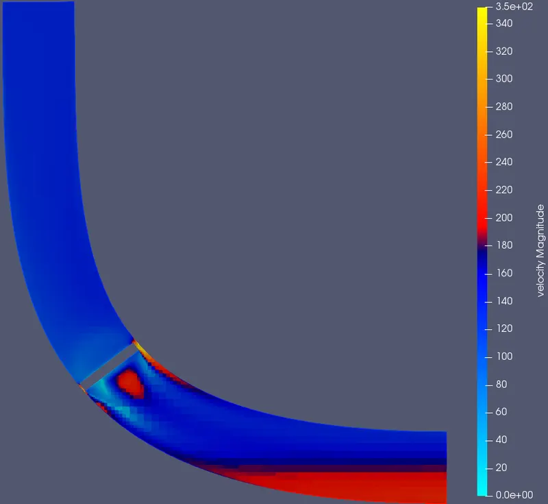
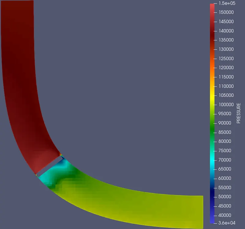
The following images show the contours asked for, for analyzing and seeing the results obtained.
Mesh
Velocity contour
Pressure contour
Converge plots at a specific time
Velocity plot
Pressure plot
Mass flow rate plot
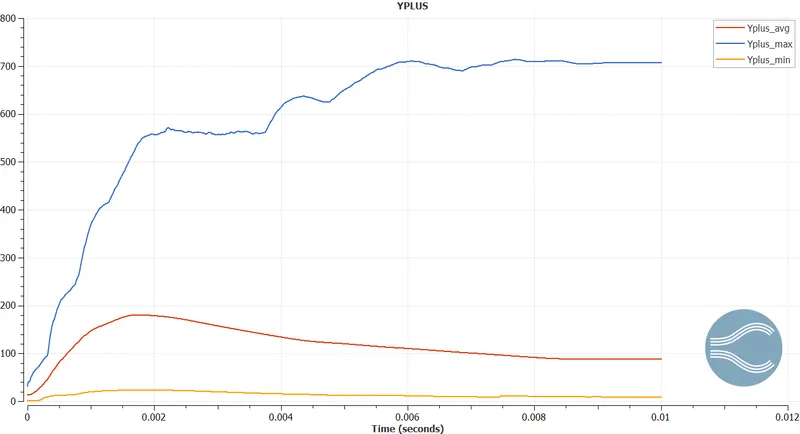
Y plus value
Cell count per processor
Memory Usage
Conclusion
NO HYDRO VIDEO
PRESSURE VELOCITY VIDEO
Y+ VIDEO
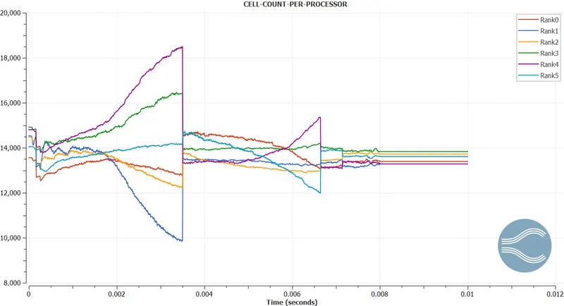
As conclusion from the results, first thing noticeable is the Y+ value has a lot of improving to do and the reason is the type of mesh used to perform the simulation is a cut-cell mesh with embedding refinement , the load balancing as well could be improved, as seen around time 0.0035 seconds the difference is very large before performing a balance load, to learn the possibilities and practice a rotating wall simulation it was a very good project, which results in a more understandable and real industry application.
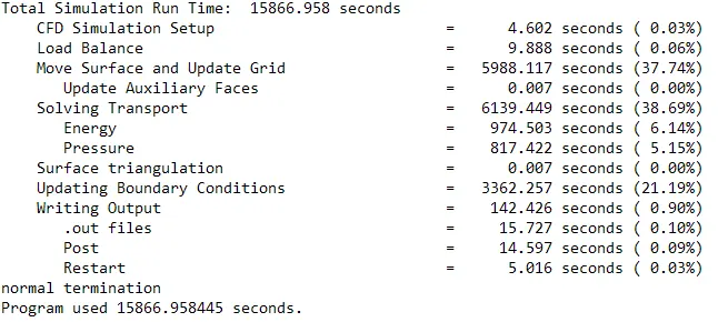
As of how I calculated the timings, the dt was an adaptive step time according to the CFL numbers for various changing variables, which depending on the desire or calculated time of the vale opening and closing the postprocessing saving time must be according on the desire accuracy and available step times or time in general.
TIME ANALYSIS
References