Week 4-1D Element Creation Challenge
AIM : To create 1D elements on the component with given cross-section, Dimensions and DOF using Hypermesh
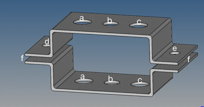
Specfication of the Component :
a. Rod element:- with only translational DOF and RBE2 link
Cross-Section: BOX- Dimension a= 12 mm
dimension b=10 mm
Thickness t= 0.75 mm
b. Beam element:- with all DOF and RBE3 link
Cross-Section: I Section- Dimension a= 8 mm
Dimension b= 10 mm
Dimension c= 8.5 mm
Thickness t1= 0.75 mm
Thickness t2= .6 mm
Thickness t3= .6 mm
c. Bar element:- with only x and y DOFs With RBE3 link
Cross-section: CROSS section- Dimension DIM1= 5 mm
Thickness DIM2= 1.2 mm
Dimension DIM3= 10 mm
Thickness DIM4= 1.2mm
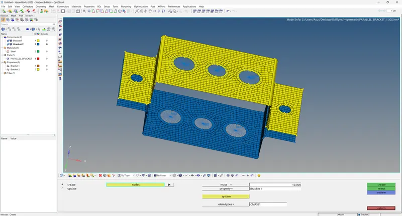
d. & e. apply the mass of magnitude 10 with RBE2 link
f. Join the two components with Spring elements .
PROCEDURE:
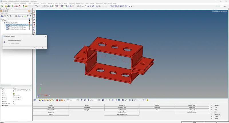
1. Import the geometry into the workspace using the import Geometry option and selecting the IGES file type, then delete the wireframe model.
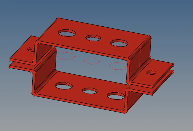
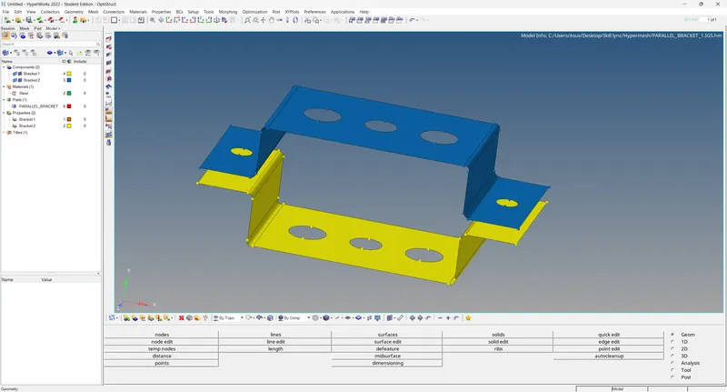
2. Select the component and create a mid surface for the top component (bracket 1) by making it current selection. Similarly select the component and create a mid surface for the bottom component (bracket 2) by making its current selection.
3. Create steel material card and assign it to the necessary component.
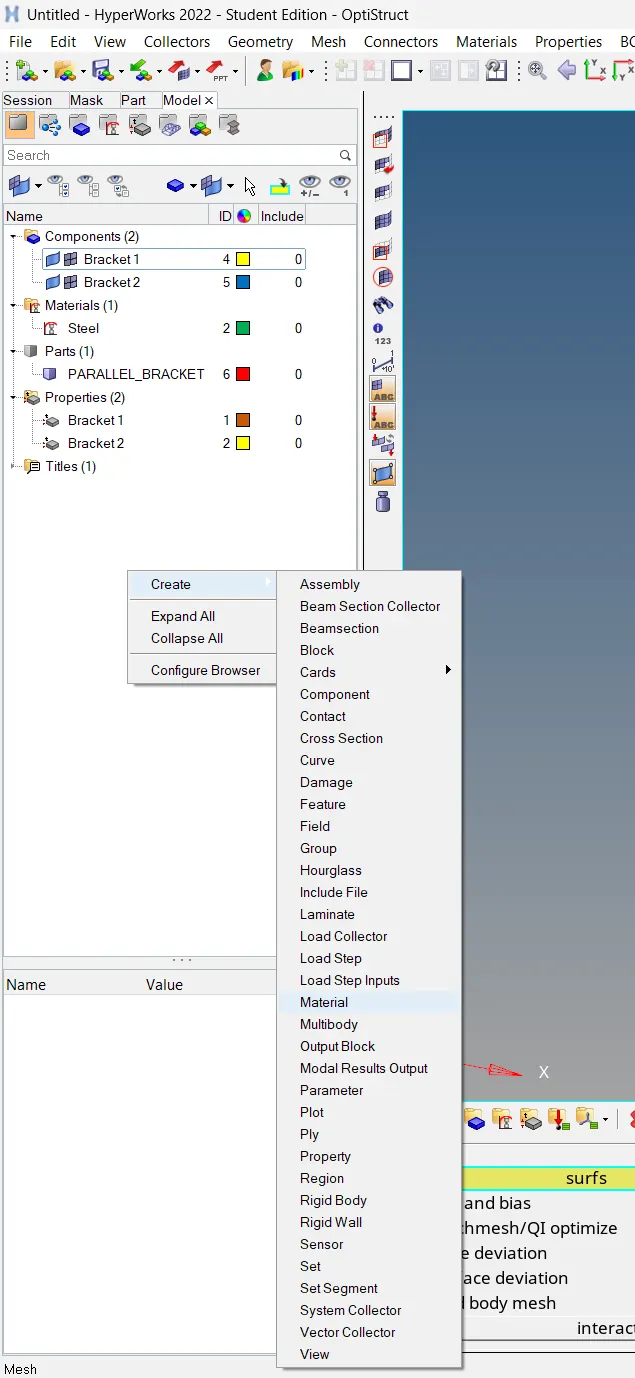
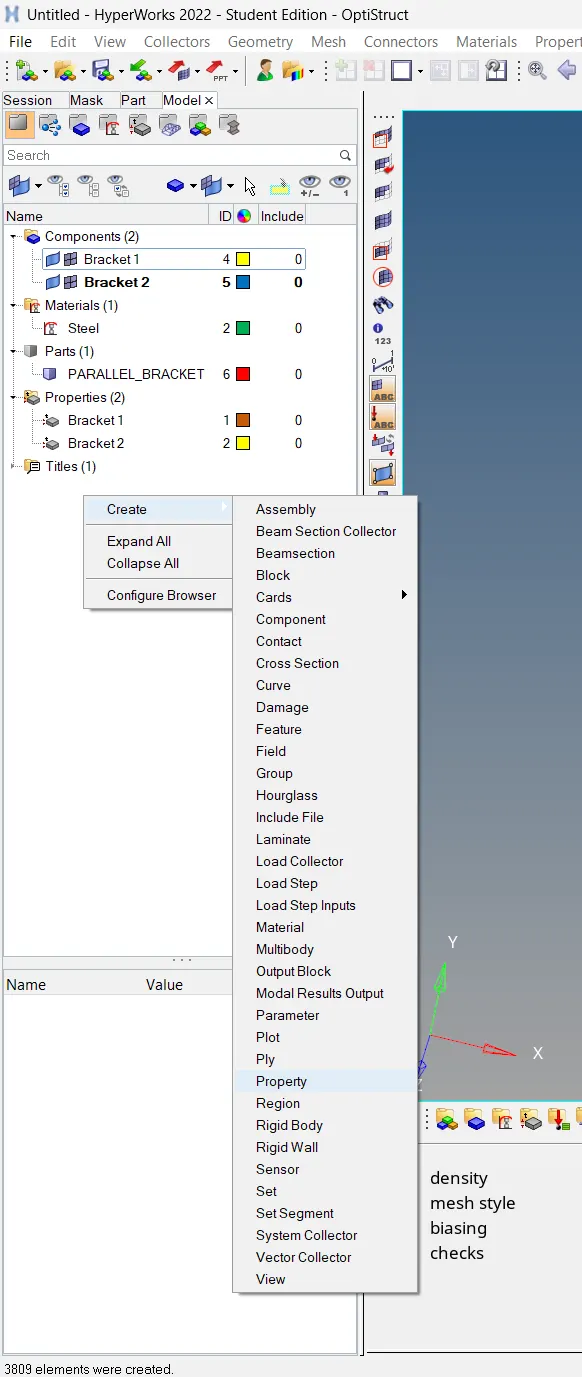
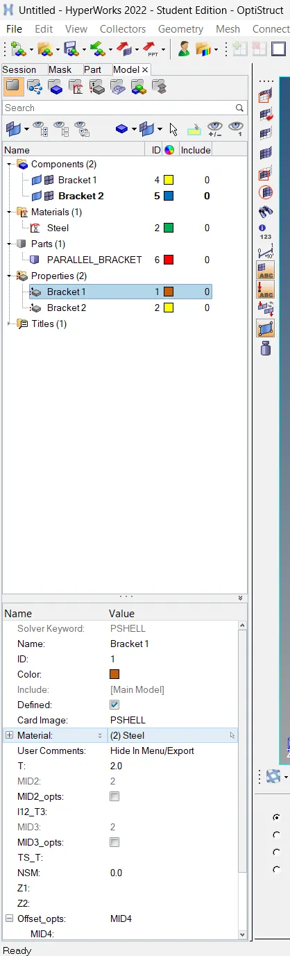
4. Create Property cards and assign it to the respective component.
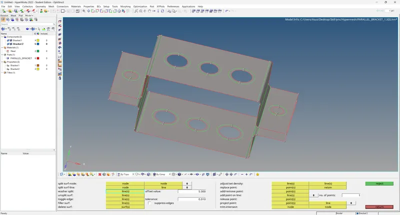
5. Washer split needs to be created around the holes to obtain a smooth mesh flow.
6. 2D mesh of the given element size is created on the model using the automesh command in the 2D option window. The mesh generated is smoothened by adjusting the number of nodes on the hole section.
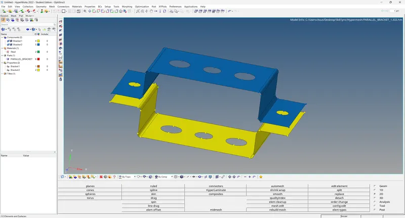
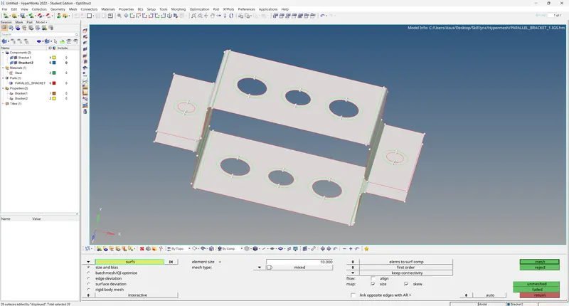
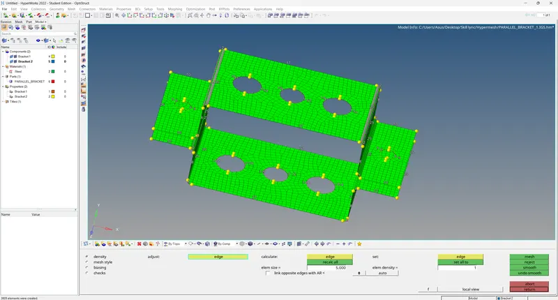
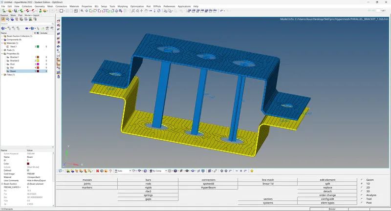
7. The two bracket are joined using the 1D RBE2 and RBE3 connectors with the respective DOF (degree's of freedom) constrained as shown in the below figure.
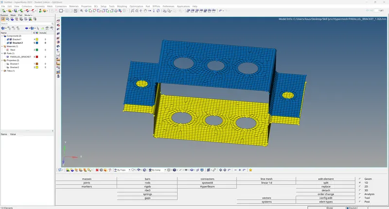
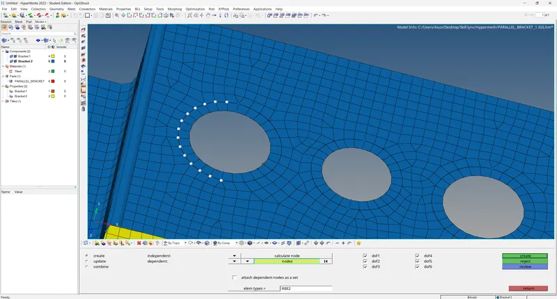
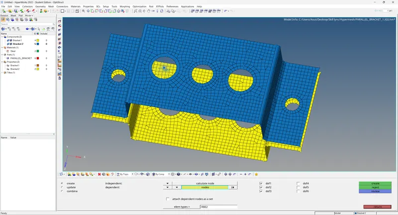
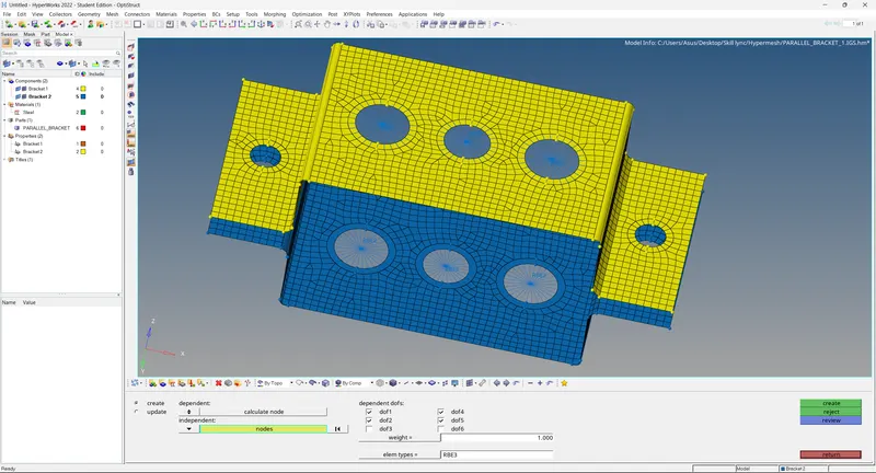
8. The mass is added to the respective connectors as shown in the figure below.
9. To Create the 1D element, go to the hyper beam tool and select the respective cross-section for creating the 1D element and give the assigned dimension to the geometry as mentioned in the specification.
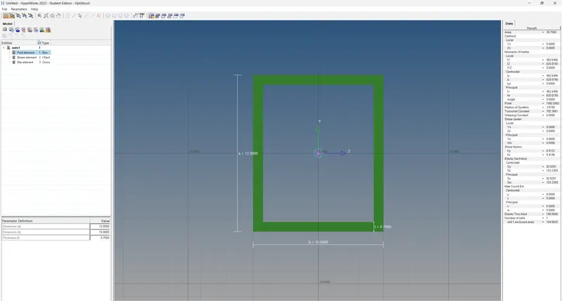
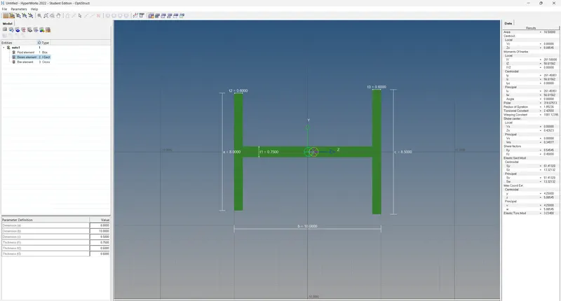
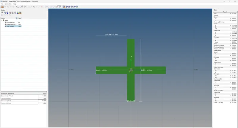
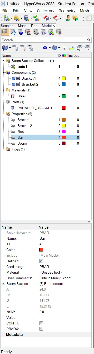
10. The created cross section and the material is updated with their respective property section as shown in the figure below.
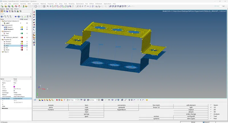
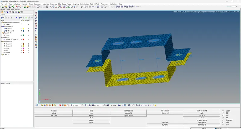
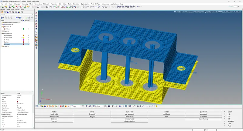
11. The 1D joints created are visualized in a detailed manner by selecting the option '1D detailed element representation'.
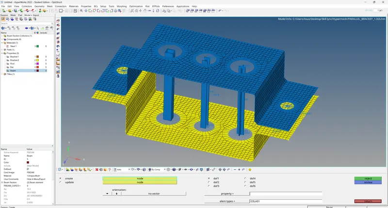
12. The two brackets are connected using the spring joints at several sections as shown in the figure below.
13. The model is represented in the 2D form by selecting the option '2D detailed element representation'.
Conclusion
- Mid-surface extracted for the given component and Created Mesh on the mid-surface.
- Applied required connectors on the 1D Element ( RBE2, RBE3, ROD, BAR, BEAM , SPRING etc ) to the respective places.
- Assigned required mass on the respective connectors.
- Assigned different Cross-section and property to the created 1D elements.
- Represented the final model in the 2D detailed view.