Week 4-1D Element Creation Challenge
Aim- To practice 2D mesh & learn what are 1D elements & how to create them in Hyperworks.
Objective- Meshing for the given component & Creating 1D elements of given crossections.
a. Rod element:- Translational DOF should be Constrained with RBE2 link
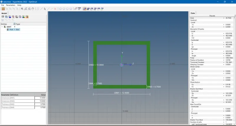
Cross-Section: BOX- Dimension a= 12 mm
dimension b=10 mm
Thickness t= 0.75 mm
b. Beam element:- All DOF should be constrained with RBE3 link
Cross-Section: I Section- Dimension a= 8 mm
Dimension b= 10 mm
Dimension c= 8.5 mm
Thickness t1= 0.75 mm
Thickness t2= .6 mm
Thickness t3= .6 mm
c. Bar element:- Constrain only x and y DOFs With RBE3 link
Cross-section: X section- Dimension DIM1= 5 mm
Thickness DIM2= 1.2 mm
Dimension DIM3= 10 mm
Thickness DIM4= 1.2mm
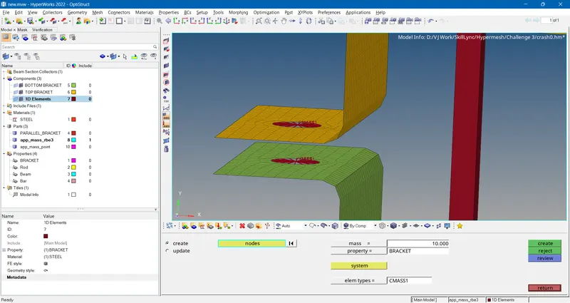
d. & e. Apply the mass of magnitude 10 with the RBE2 link.
Procedure-
- The given model is imported.
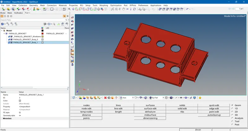
- Checked the model visually by switching the view to by 3D topo for any unconnected edges & deleted the excess data such as wireframe & solid model. Only surfaces were kept.
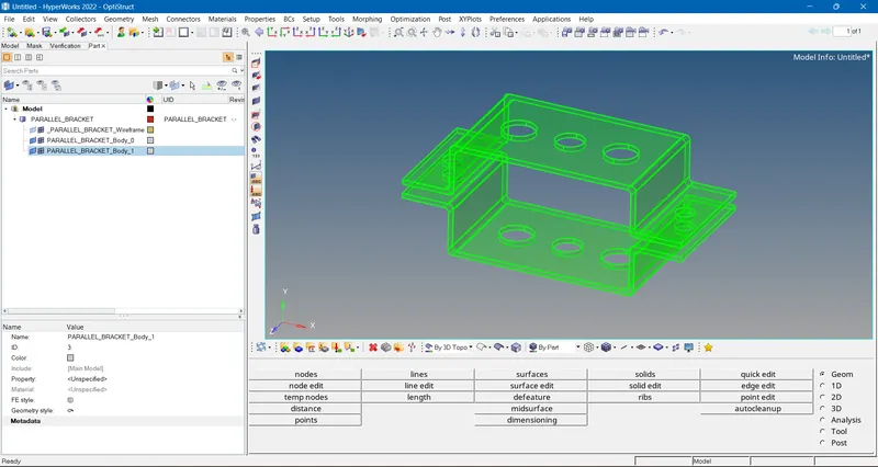
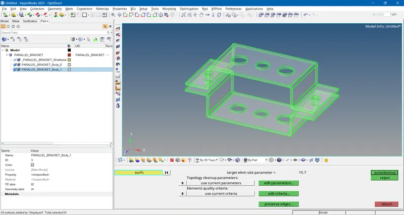
- Performing an autocleanup to remove pinholes.
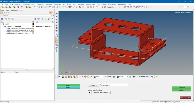
- Measuring the dimensions of the brackets to check the thickness.
- The midsurface is extracted by using midsurface option in geometry tab for both the brackets individually selecting each.
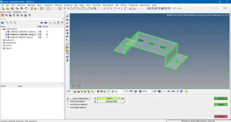
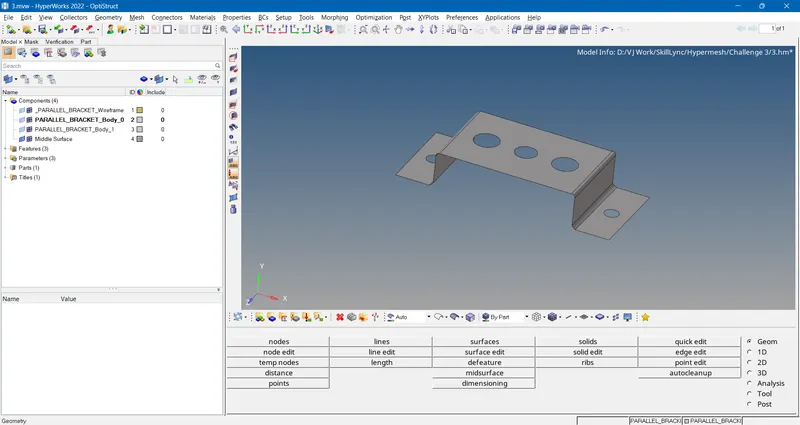
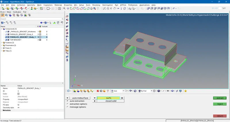
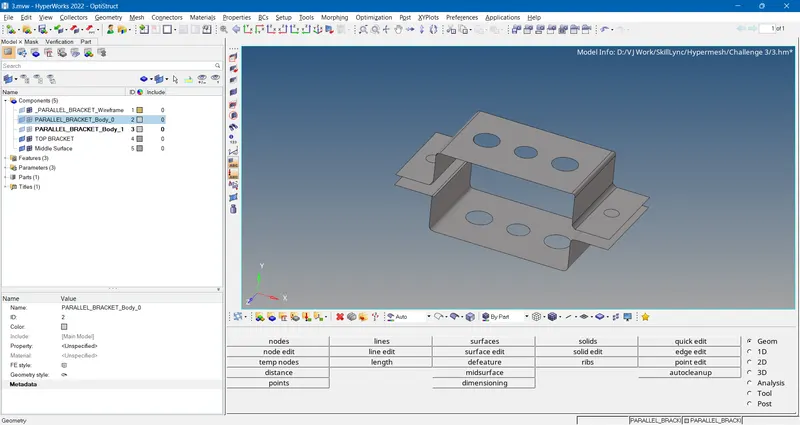
- Renamed both the created midsurfaces as top & bottom bracket.
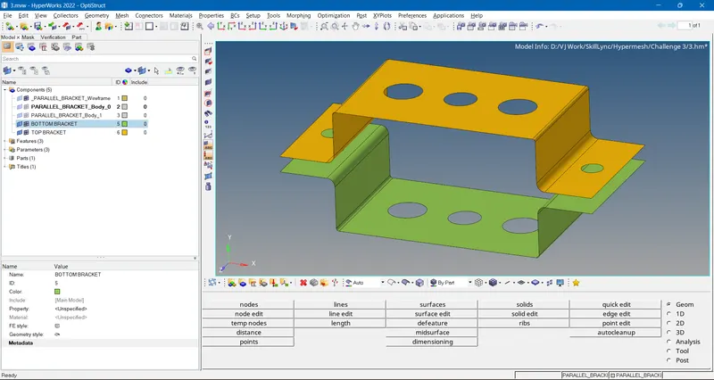
- Meshing both the midsurfaces by using the mesh automesh option from 2D tab. The mesh element size were kept to 5 as given.
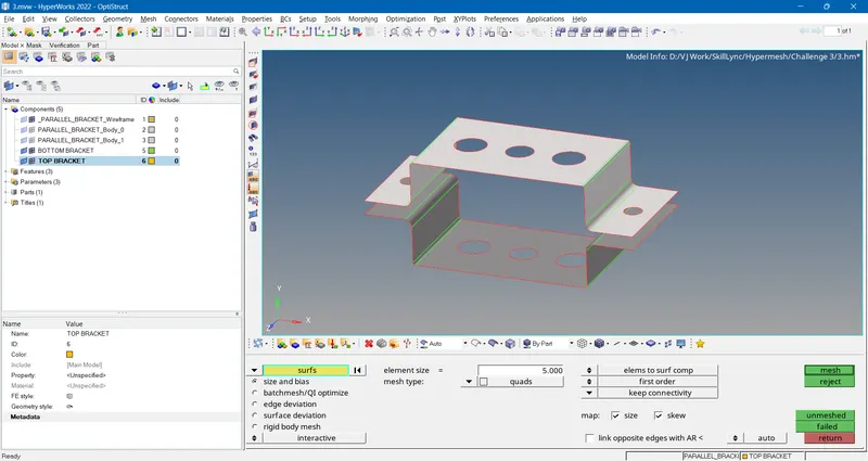
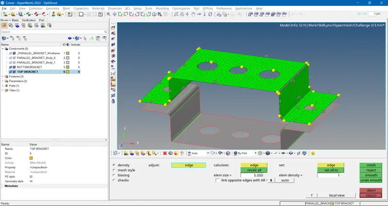
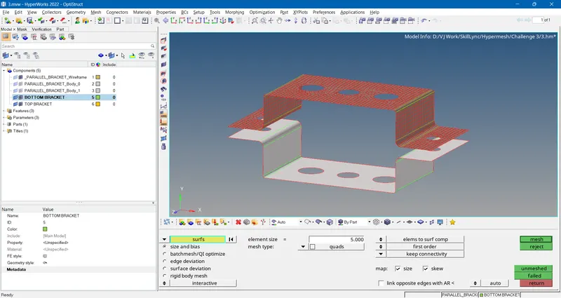
- Checking the created mesh for quality failures from quality index options available in 2D tab & cleaning up the failed elements using the cleanup tools.
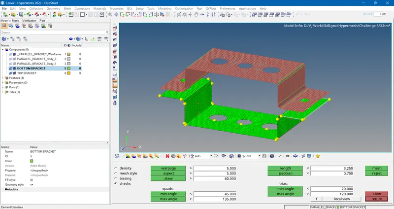
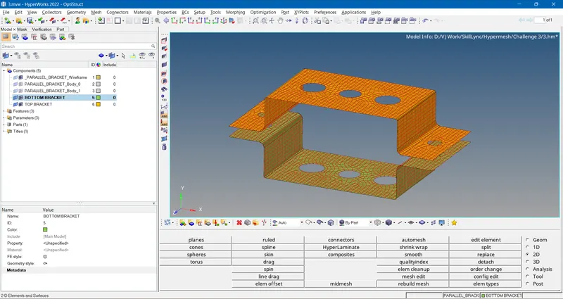
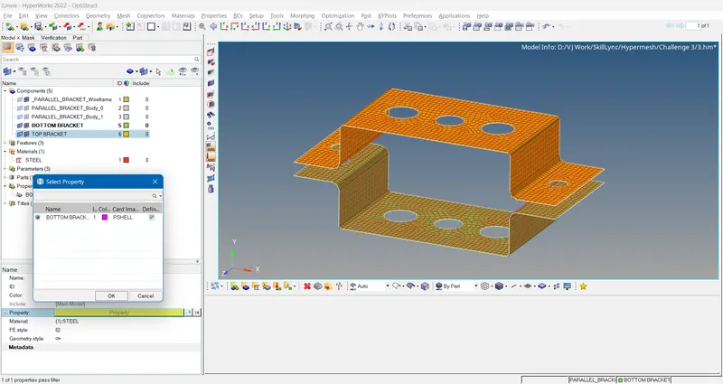
- Creatng & assigning the property & material to the midsurfaces using the create/property option by right clicking in the browser area.
- Switching the 2D element detailed representation ON for clear view of mesh in 3D.
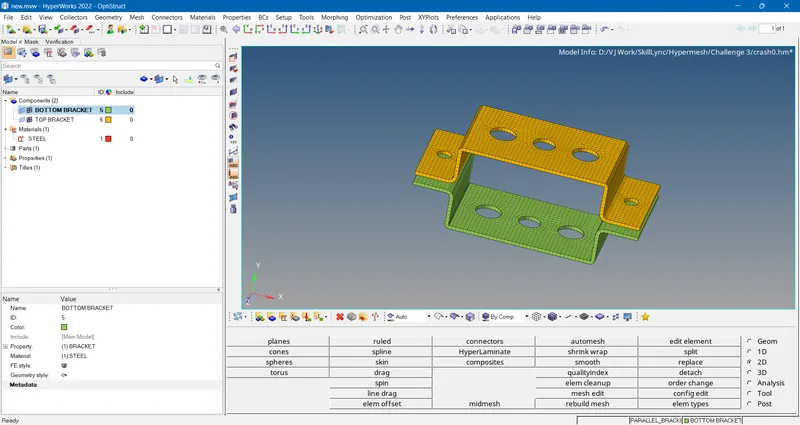
- Now to create 1D element-
- First RBE2 element is created at the given point using rigids option in 1D tab. Setting the independent node to calculate option &selecting the dependent nodes, by which hyperworks automatiocally finds the central node, Selecting the DOF only which we have to restrict , in this only the translation DOF has to constrained so the DOF 1,2 & 3 are selected.
- Then click create.
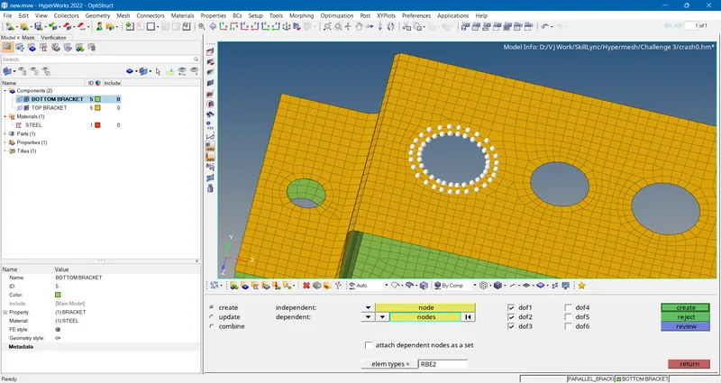
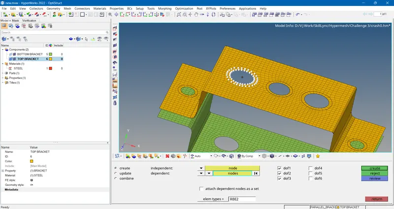
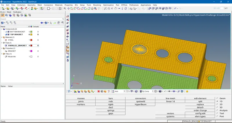
- Similarly for other bracket also created.
- Then RBE3 is created using RBE3 option in 1D tab & following the method as for RBE2 creation, only in this case all DOF are constrained as given.
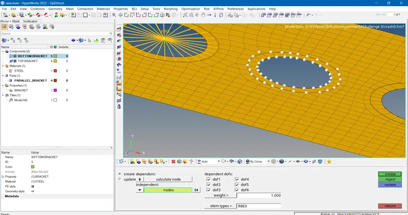
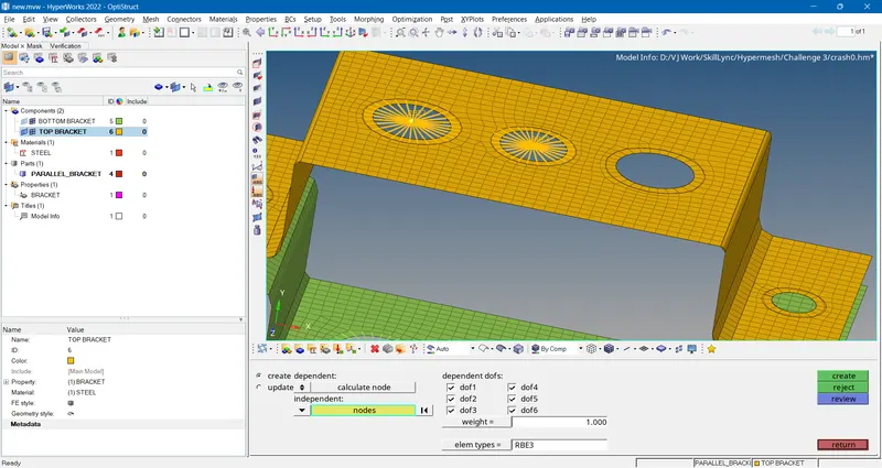
- Similar for other bracket,
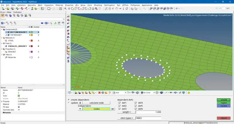
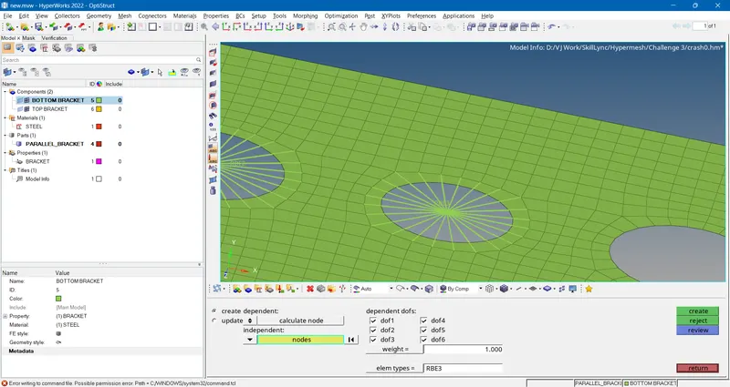
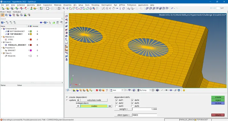
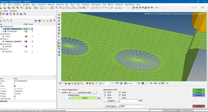
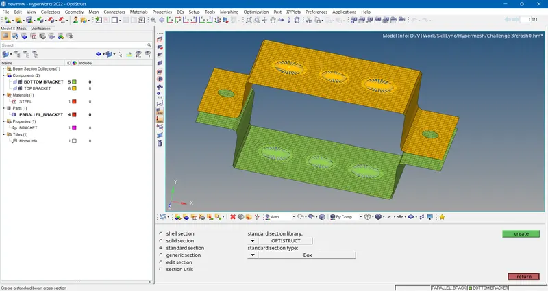
- All 1D elements created. then to create the bar, rod beam section, the hyperbeam option in 1D tab is used.
- selecting standard section, solver as optistruct & section as box & clicking on create, it opens an hyperbeam window where we can create the various cross sections.
- First for rod element box section is created with given dimensions,
- Then a beam section is created by right clicking in the left window as shown.
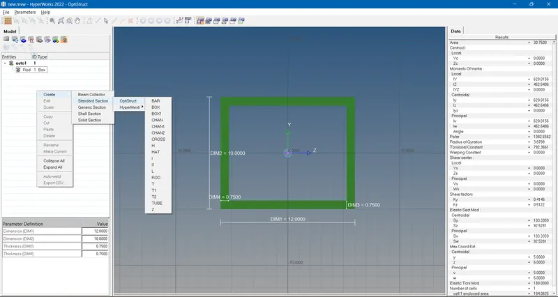
- Selecting I section & giving the dimensions.
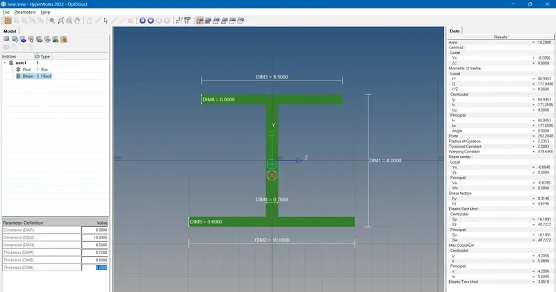
- Similarly bar secton is also created with cross section as a cross & giving the dimensions.
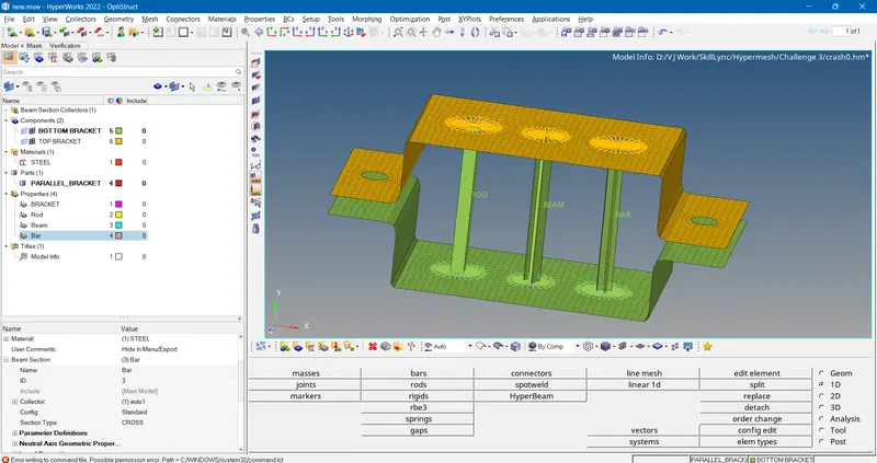
- Then returned to model view by clicking model view option & assigning properties to each bar, rod & beam element. The respective crosssection is selected under property card for each element.
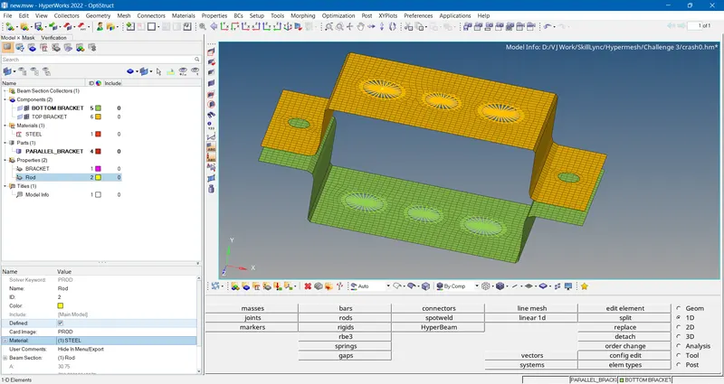
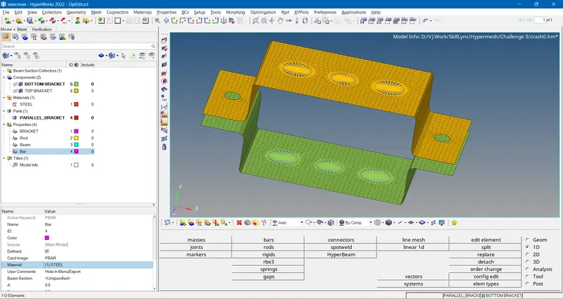
- Then 1D rod, bar & beam elements are created by rod & bars option under 1D tab.
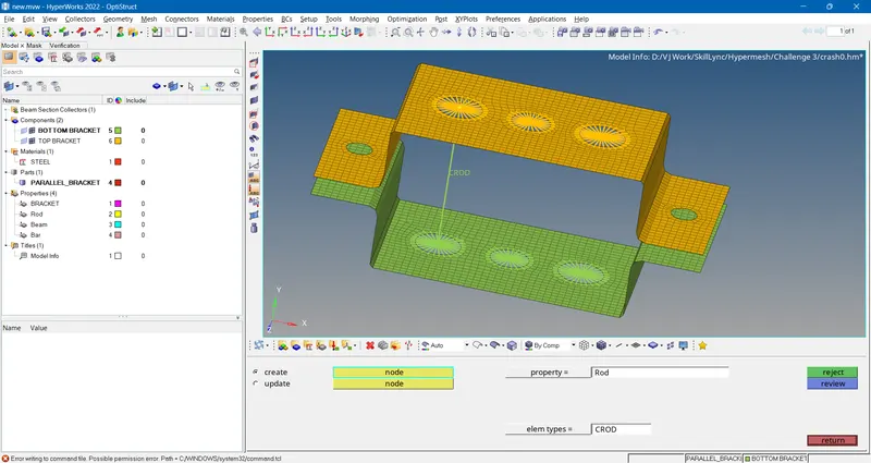
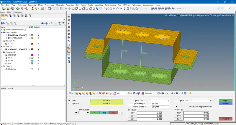
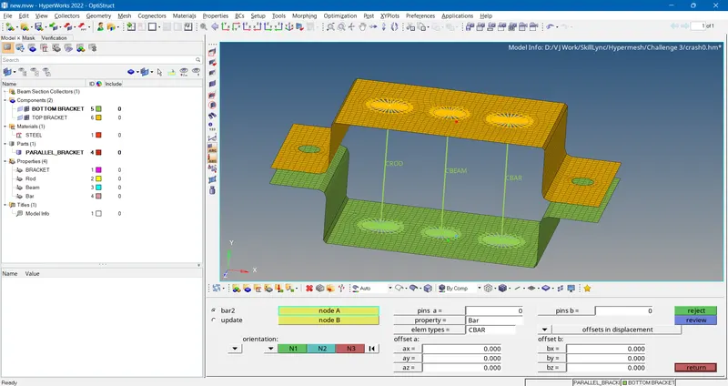
- For clear view of 1D elements the 2D detailed representation option is turned ON.
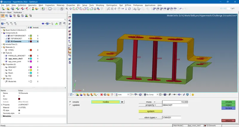
- Then the mass is applied by creatiing RBE3 elements & selecting the nodes. From the masses option under 1D tab
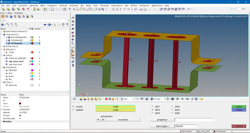
- The brackets were then joined by creating spring elements betweein them. From the spring option under 1D tab
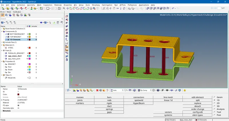
- The final geometry with mesh & 1D elements-
Conclusion-
- Successfully created the 2D mesh with good quality.
- Learned the 1D elemets & successfully created them in hyperworks.
- Learned the applications of 1D elements. Such as Rod elements are used under Torsion & compression, the beam elements are used for components subjected to bending & the bar elements are used for bending when there is constant cross section.