Week 4-1D Element Creation Challenge
Q1) Mesh the Given component with the Size of 5 Units. Create 1D elements on the following component with given cross-section and DOF
ANSWER:- All line elements, whether straight or curved, are called 1D element in which they have translational and rotational displacement functions
Download Given model and check file format, Import in hyper works IGES format
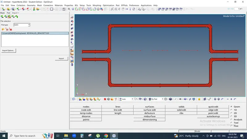
We need to clear un-necessary lines then we move for midsurfacing
Geometry < Midsurface < Auto midsurface < select surface < extract
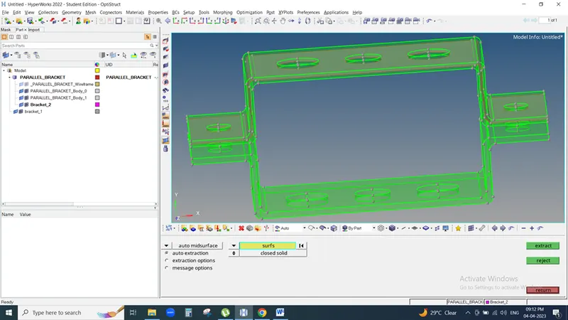
In Component Midsurface is generated then rename to Bracket_1 & again one component create similarly rename to Bracket_2
and extract 2nd Bracket also but due to system it crate new midsurface so we need to move this midsurface to Bracket_2 before moving operation we need to delete solid surface
Otherwise solid surface also move for that we need to follow following path
Delete <surface < delete entity 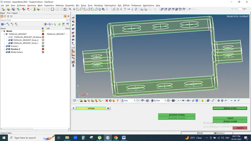
For move midsurface
Tool < Organize < collector < surface<Move
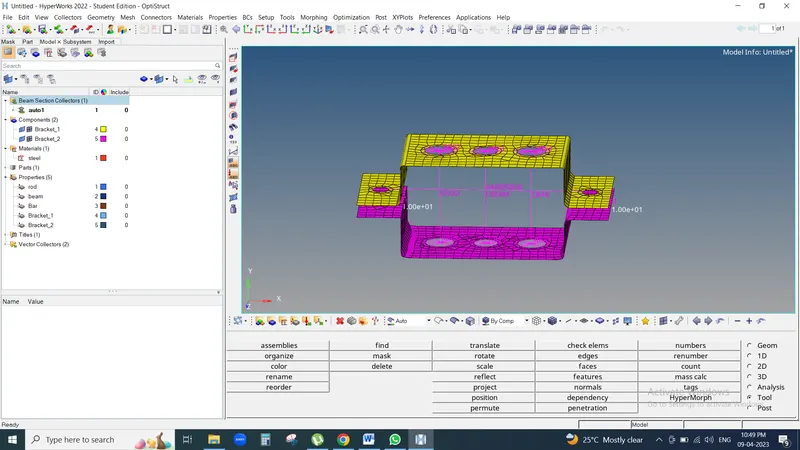
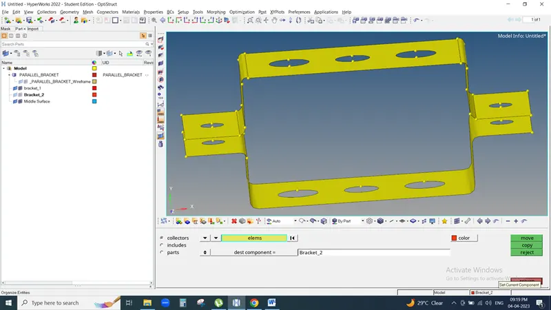
Then we move for Auto-clean-up & Auto-Mesh
Geometry < Auto clean-up <Surface < Auto clean up
Geometry < Quick edit <washer split <offset value 5 & middle click
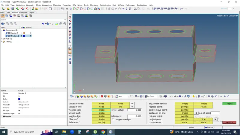
For Meshing
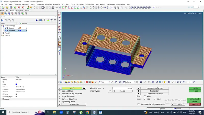
2D < Auto mesh <surface < element size 5 <Mesh
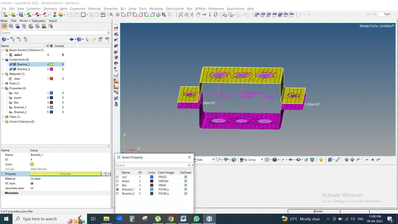
For component we need material & Property so we create Bracket_, Bracket_2 in property select card image is Pshell & material as steel
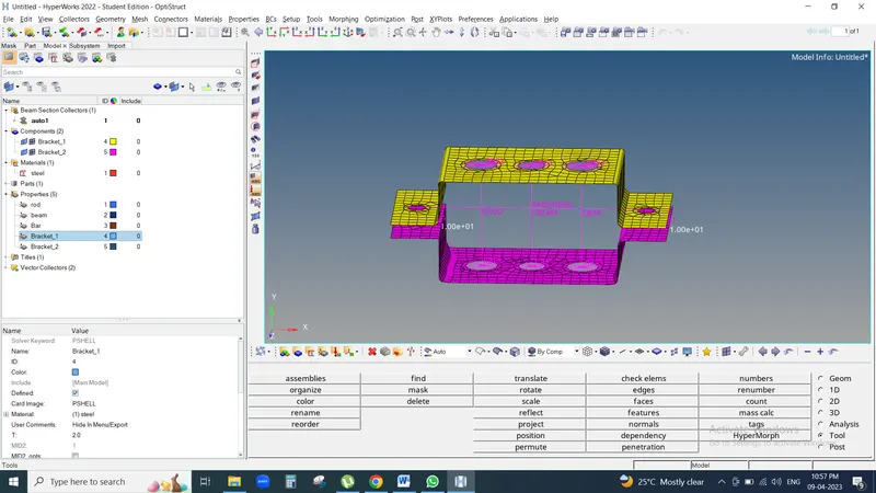
In component Bracket_1 & bracket_2 select Property respectively material automatically show
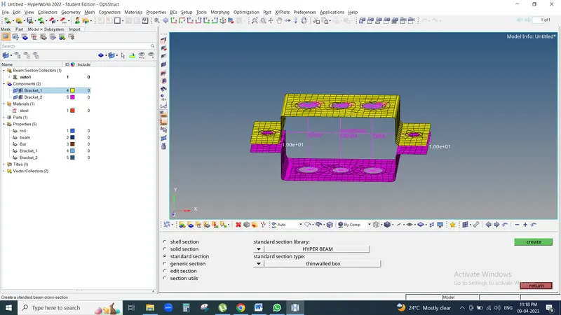
We need to create 1D element in Hyper bam < standard section < standard section library <hyperbean < standard section type < standard I section
Bar element
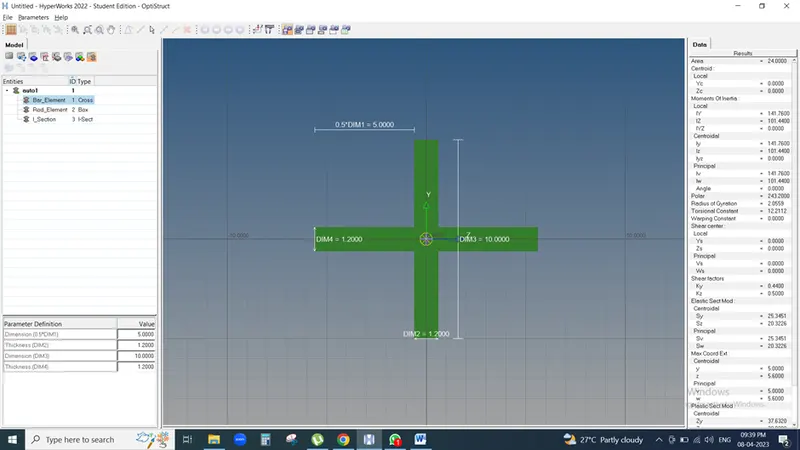
Box element
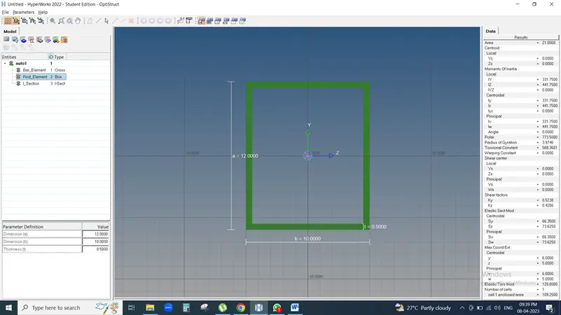
I-section
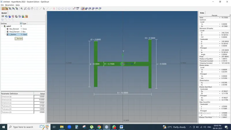
Again go to model view & create ROD, BAR & BEAM property
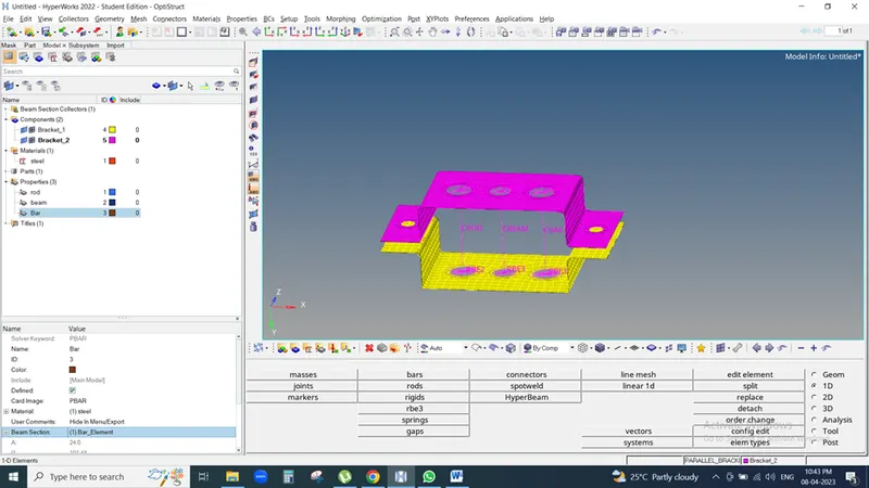
As per requirement we need to create
a. Rod element: - Translational DOF should be constrained with RBE2 link
Creating RBE2 Node
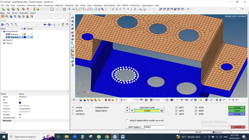
Goto 1D>>rigid>>Select nodes>>Click on create (This is for one node)
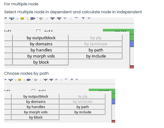
Select nodes bye path as shown below and then click create. This is called RBE2 link not element because it is cluster of elements.
b. Beam element:- All DOF should be constrained with RBE3 link
Goto 1D>>RBE3>>select nodes>>Click on create
c. Bar element: - Constrain only x and y DOFs with RBE3 link
Goto 1D>>RBE3>>select nodes>>Click on create
Select property id for Rod is PROD & select material Steel similarly do for BAR & BEAM
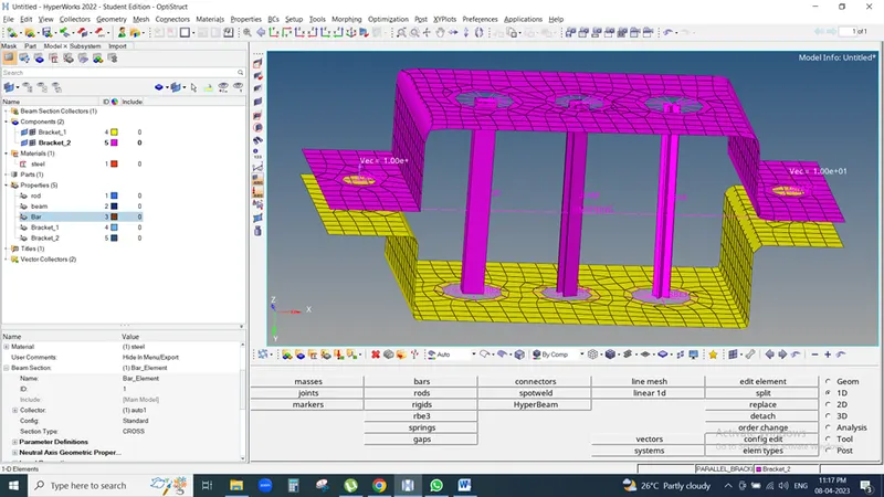
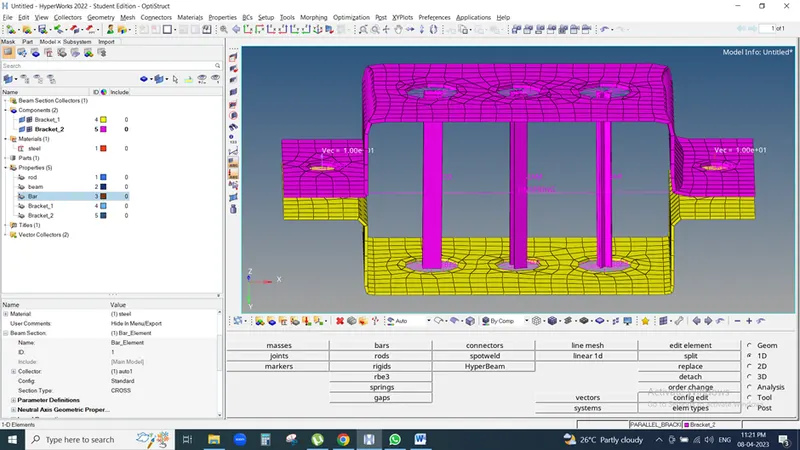
1D>>Bar>>Bar2>>Select nodes>>Choose ‘CBAR’ as element types>>give orientation
Rod
1D>>Rod>>Create>>Select nodes>>choose ‘CROD’ as element types
Beam
1D>>Bar>>Bar2>>Select nodes>>Choose ‘CBEAM’ as element types>>give orientation
Putting mass on Nodes
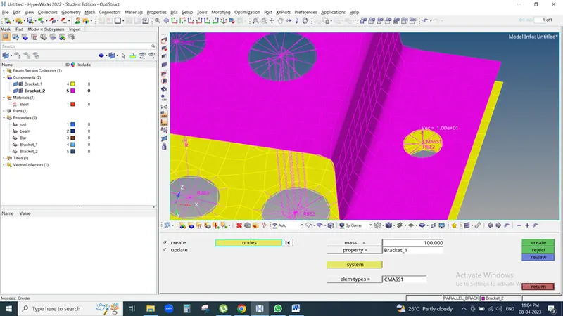
Go to 1D>>masses>>create>>select node, mass, property, element type>>click on create
Add spring element
1D>>springs>>Select nodes
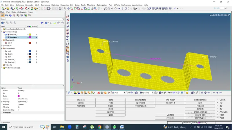
2D detailed element representation is as shown below