Week 4-1D Element Creation Challenge
Objectives:- 1. To create midsurface and mesh the model.
2. To create 1D element on component with given cross-section and DOF.
Procedure:-
- Import the geometry and cleanup the geometry.
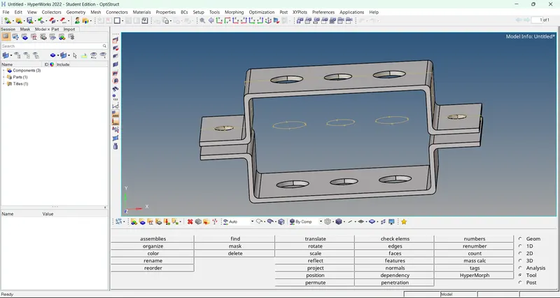
- For creating midsurface, select 'surfaces' from 'geom' section and click on extract. The midsurface is generated in model.
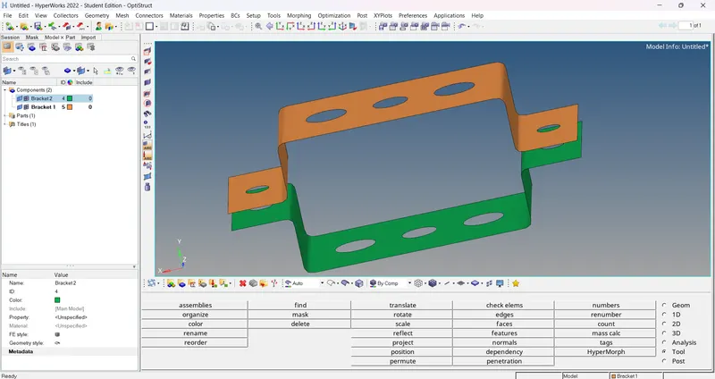
- After that delete the solid surfaces using delete option. Only midsurface is remaining. Then create components for this midsurface. Also created material and property for that component.
- Assign property and material to that component or midsurface.
- Then go to 'quick edit' in 'geom' section. Split the washers using 'washer split' option for better mesh flow. Then enter the offset value and click on washer edge.
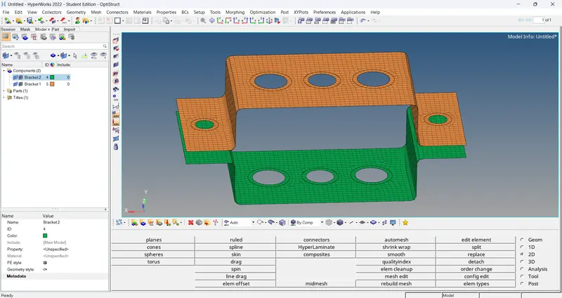
- Then go to 2D section, select 'automesh' option for meshing. After that enter element size and mesh type. Then enable align and size option and select the surfaces which is to be meshed. Then click on mesh 2D mesh is generated over the surfaces.
- If mesh flow is not proper, then go to 'rebuild mesh' in 'geom' section. Then select the faces where mesh flow is bad. And then edit criteria and parameters. Then click on rebuild. The proper mesh flow is deployed on surfaces.
- For creating RBE2 links at given holes, go to '1D' section and select 'rigids' option. Then select the nodes and enable the DOF which is required. Then click on create, the RBE2 element are created.
- Similarly for RBE3 elements, select 'RBE3' option. Then select the nodes and eneable the DOF which is required and click on create. The RBE3 element is created.
- After creating RBE2 and RBE3, we have to create 1D elements. For that, cross-section is need to create. Go to '1D' section and select 'hyperbeam' option. Then select standard section library as 'hyperbeam' and select section type.
- After that software diverted to new window i.e. hyperbeam view. First we create cross-section of rod element. So create a new box section and enter the dimension in parameter defination, the rod cross-section is created.
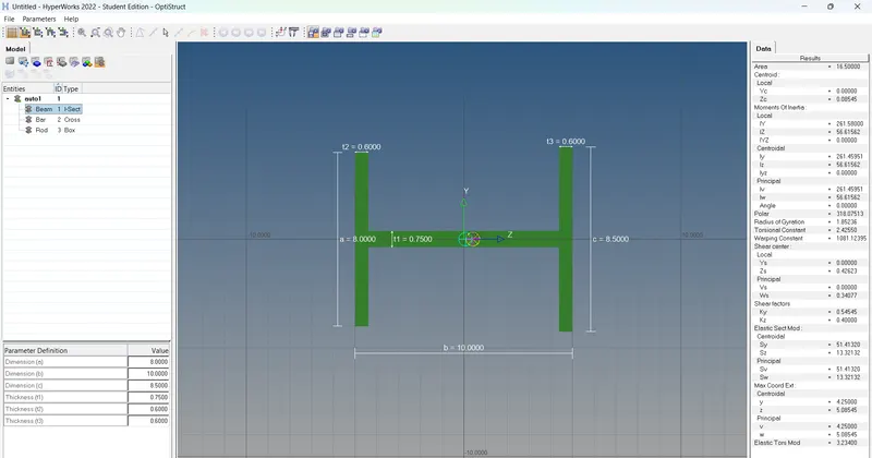
- Accordingly we create 'I-section for beam element' and 'X-section for bar element'. After creating cross-section, go to model view.
- After creating cross section, create component for this cross-section. And also create property for that components. Then assign material and card image to that property and assign property to that component.
- Then create springs at required face using 'spring' option in '1D' section. Also create component and property to the spring. Then assign material and card image to property and assign this property to spring component.
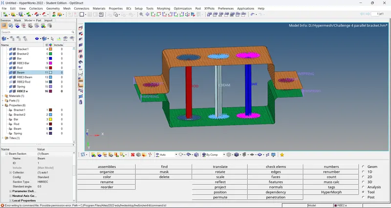
- Then create RBE2 elements at given holes and assign mass to them by using 'masses' option in '1D' section. And final model is ready.
Conclusion:- We create midsurface and mesh the model and create 1D element on component with given cross-section and DOF successfully.