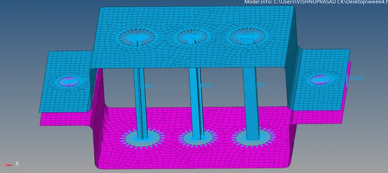
AIM: To mesh the given component and provide 1D elements on it.

PROCEDURE:

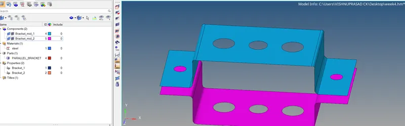
1.Mid suface of the upper portion is taken by using mid suface option in the geometry and component name is assigned to it

2.Mid suface of the lower portion is taken and the component is renamed.
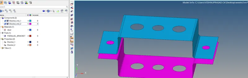
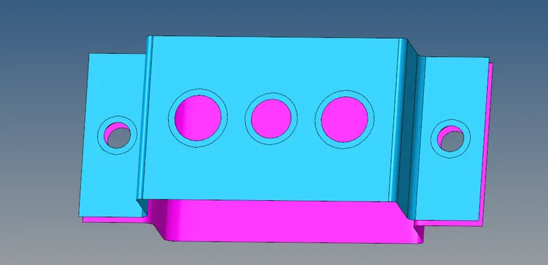
3. Since the mid surface contain holes washer split option is used from quick edit to have a better mesh flow.
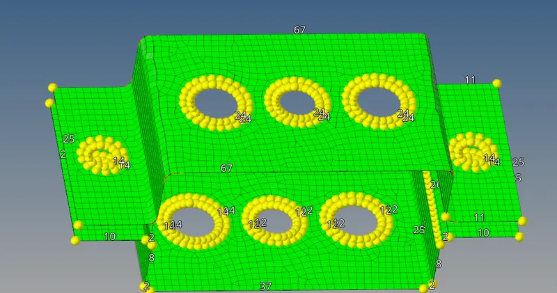
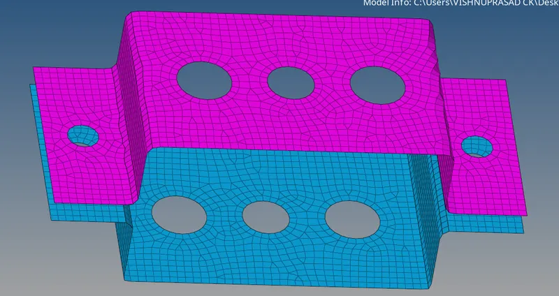
4. Meshing is done on both the parts with a length of 5 and mesh flow is made bettter near the hole sections.
5. Material id is provided and steel is selected as the parent material.

6. Property is provided to the component and thickness and material is also assigned to
   it
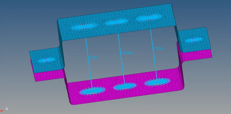
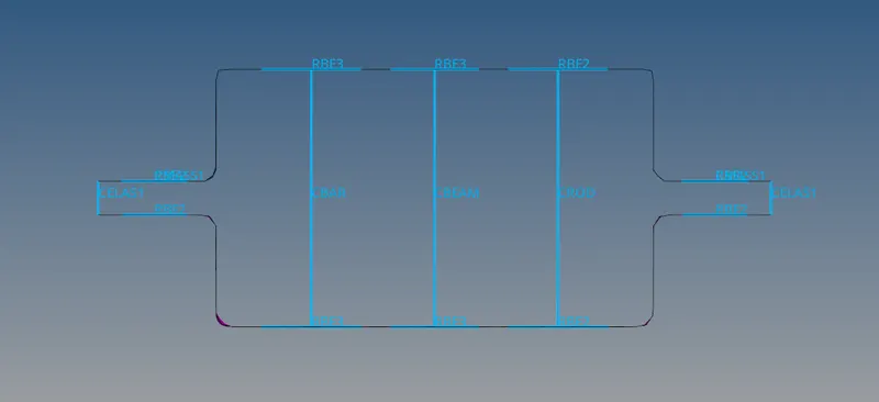
7.At position 'a' RBE2 link is provided from rigid option in 1D.Nodes are selected in
  pathway by using multiple nodes option with degree of freedom constrained for transalation in three axis

8. Similarly at 'b' position RBE3 linkage is provided from RBE3 option from 1D.Nodes are selected by window selection and degree of freedom restricted in all possible movements.

9. At position 'c' RBE3 linkage is provided, with degree of freedom restricted to x and y axis.

10. At 'd'  & 'e' position RBE2 linkage is provided from rigid option in 1D.

11. At postion 'a' rod element is provided from the Rod option in 1D by selection of  two
    master  nodes in RBE2 linkage and element type CROD is selected.

12.At position 'b' beam element is provided by selecting element type as CBEAM from BAR option.Two nodes are selected and orientation is provided.

13. At position 'c' bar element is provided by selecting element type as CBAR from BAR in
    1D option. Two nodes are selected and orientation is given.
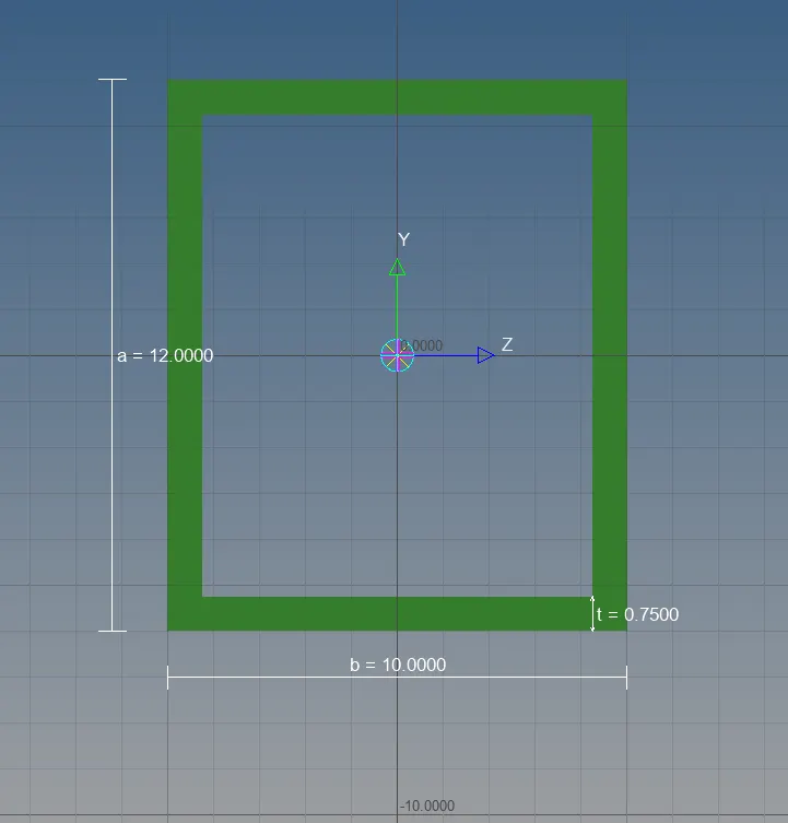
 14. Cross section of rod element is BOX , which is made by using the hyper beam option
     in 1D.
       In hyper beam option, standard cross section - thin walled box is selected and
       required dimensions are given to obtain the desired section.

 15. Cross section beam element is I-section, which is done using the hyper beam option
    in 1D.
           Hyper beam-standard section- I section, is selected and the dimensions are
           provided to get the desired section.
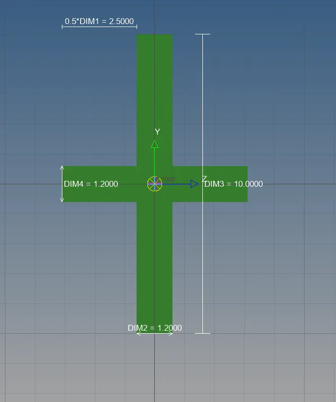
 16. Similary cross section of bar element is '+' section, which is made by using the
     hyper beam option  in 1D.
        In hyper beam option, '+' section is selected and dimensions are provided to
        obtain the section .

 17. Mass of magnitude 10 is provided on the nodes of RBE2 linkage in position 'd' & 'e'.
     This is done by using masses option in 1D, required magnitude is given and node is
      selected to create mass on node.

18. At gap 'f', spring connection is provided from spring option in 1D by selecting end
    nodes of upper and lower positions in two sides
 19. Property is assigned for rod,bar and beam element and respective cross section is
     also assigned to the property