Week 4-1D Element Creation Challenge
AIM: To create a mesh on a given component & that need to be created with 1D elements for different concerns & purposes.
Objective:
Mesh the given model at the element size of 5 units, and create 1D elements on the components per the given composition of cross-section & DOF.
Given Data:
a. Rod element:- Translational DOF should be Constrained with the RBE2 link
Cross-Section: BOX- Dimension a= 12 mm
dimension b=10 mm
Thickness t= 0.75 mm
b. Beam element:- All DOF should be constrained with the RBE3 link
Cross-Section: I Section- Dimension a= 8 mm
Dimension b= 10 mm
Dimension c= 8.5 mm
Thickness t1= 0.75 mm
Thickness t2= .6 mm
Thickness t3= .6 mm
c. Bar element:- Constrain only x and y DOFs With the RBE3 link
Cross-section: X section- Dimension DIM1= 5 mm
Thickness DIM2= 1.2 mm
Dimension DIM3= 10 mm
Thickness DIM4= 1.2mm
d. & e. Apply the mass of magnitude 10 with the RBE2 link
f. Join the two components with Spring elements
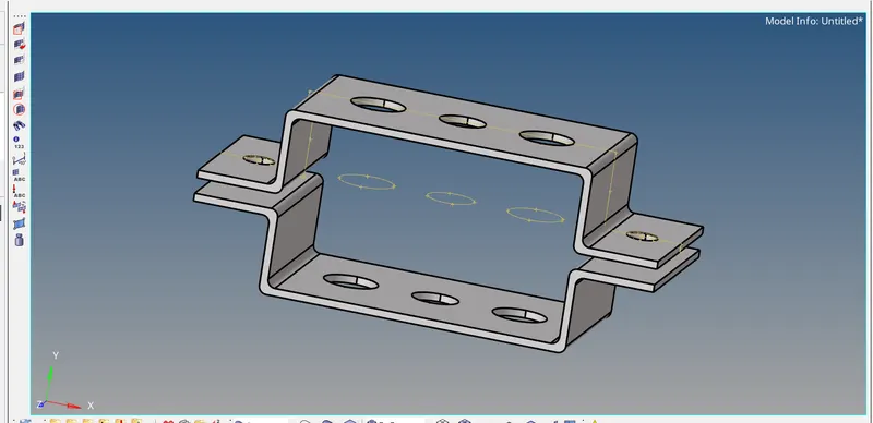
Image shown below is the component were we have to apply the condition which are mention above.
Procedure:
Import :
Need to import the model as IGS files
Extract the Mid surface:
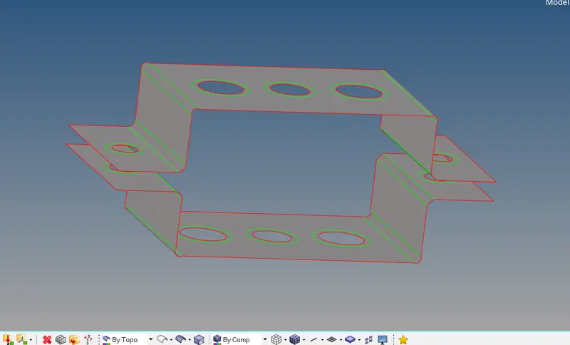
Before Extracting, the mid surface, delete the solid components of the mode, then choose "Geom -> Midsurface -> Auto extraction" and select the area to be extracted.
Extract the mid surface for the model by using the midsurface option in the geometry panel. for both brackets, we have to extract the midsurface separately. we use the auto midsurface option for creating mid surface whereas we use the extraction option as offset+ planes for creating mid surface.
And create Washer Split in the surf which has circular parts.
Meshing:
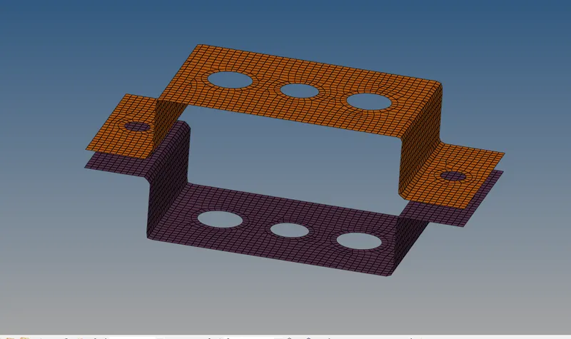
Once extracting the model, we now have to mesh the model, with the element size of 5
Before creating the meshing for a whole model, create a mesh in Washer split area to get a smooth meshing surface.
To do up the clean up the model, we can use a manual method, or else Auto cleanup is also used to create the washer Split manually into the components
Once the geometry cleanup is done, now click "2D -> Automesh -> Select the model to mesh" and get the element size as 5 with a mixed element
Then the component is meshed & and need to checkup with a quality index that they are any sort of mistake taking place according to the criteria file
1D elements:
To compute the project in the 1D element there are many criteria, but here some of the following is given for the further process.
CROD
CBEAM
CBAR
RBE2
RBE3
To compute the above 1D element first we have to create RBE elements on the meshed surface.
As per the given form of data to create Rod, Beam, Bar, Mass, Spring we have to create a construction of Rod, Beam, Bar by using the Hyperbeam.
To get into Hyperbeam Follow the procedure "1D -> Hyperbeam"
ROD element:
Condition:
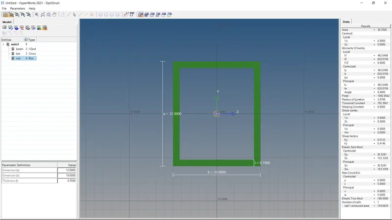
BOX:
Dimension a = 12mm
Dimension b = 10mm
Thickness t= 0.75mm
The above is the input to the Box of the Rod element,
To create it "1D -> Hyperbeam -> Create -> standard section -> Hypermesh -> Thin walled box".
Beam Element:
Condition:
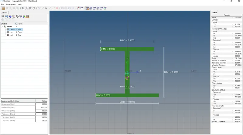
Cross-Section: I Section- Dimension a= 8 mm
Dimension b= 10 mm
Dimension c= 8.5 mm
Thickness t1= 0.75 mm
Thickness t2= .6 mm
Thickness t3= .6 mm
The above is the input to the I section element of the Beam element,
To create it "1D -> Hyperbeam -> Create -> standard section -> OpticStruct -> I section Element".
Bar Element:
Condition:
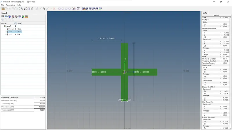
Cross-section: X section- Dimension DIM1= 5 mm
Thickness DIM2= 1.2 mm
Dimension DIM3= 10 mm
Thickness DIM4= 1.2mm
The above is the input to the I section element of the Beam element,
To create it "1D -> Hyperbeam -> Create -> standard section -> OpticStruct -> Cross Element".
Creating a Rod Element:
Once create the element in all the sections which are mentioned and we have implemented it in the model.
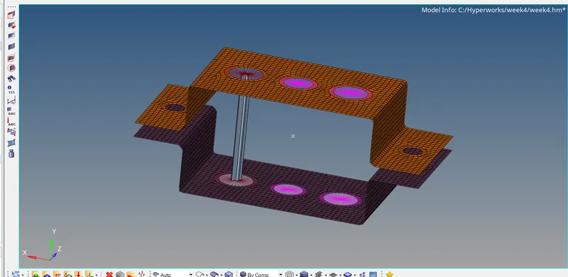
Next, create an RBE2 element in "a" element with all translational X, Y, and Z DOF 1,2,3 have been chosen.
To implement in the model we have created the RBE2 element in the "a" element.
Give a BOX cross section by using Hyperbeam Section.
Creating a Beam Element:
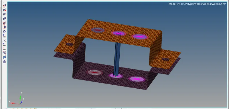
As per the requirement, "All DOF should be constrained with the RBE3 link"
Create a CBEAM element by connecting holes on the "b".
Give the I Cross section by the Hypermesh section.
Creating a Bar element:
Now we have to create the RBE3 cluster in the "C" in the bracket surface.
Create a CBAR element by connecting holes at "C".
Give X cross section by using the Hyperbeam section.
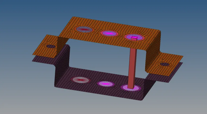
d. & e. Apply the mass of magnitude 10 with the RBE2 link.
To create the Mass element in that component, by using the RBE2 link are been used to create in the "d & e".
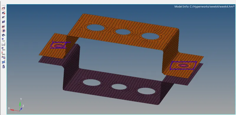
f. Join the two components with Spring elements
For joining 2 component here we used spring element, and use of RBE2 rigid element.
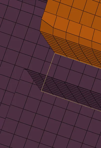
First we create a rbe2 element in the end edge of upper component and as well as bottom and then fix the spring element between them.
Conclusion:
We have done the mesh in the given component and then 1D element as per given instruct.
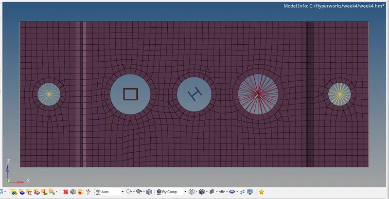
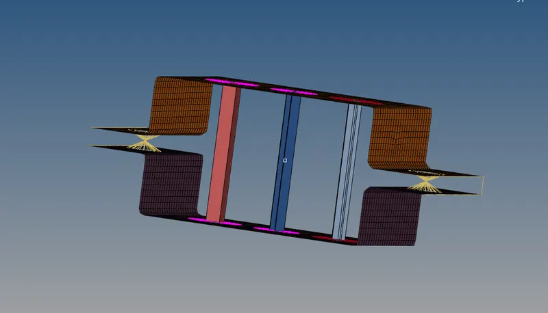
All 1D element operation have been performed and shown in the above picture.