Week 4-1D Element Creation Challenge
1. Import the given Component using the Import option in Hypermesh.
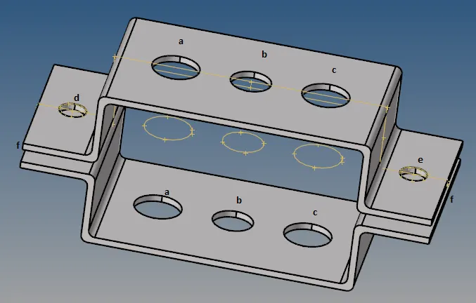
Fig: Imported Parallel Bracket Model
2. Creating a Mid-surface of the given component by using Geom-midsurface option.
3. After creating a Mid surface of the given component, Use Washer Split option and create a washer as 5mm on each pinhole.
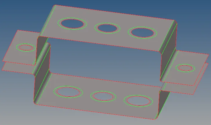
Fig: Midsurface Component
4. After Creating a Mid surface, Go to 2D-automesh option and set element size and mesh the component.
5. While meshing, Keep the number of elements on both sides of the part as equal to avoid tria & quad elements.
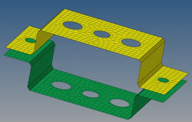
Fig: Mesh Component
6. Create Steel Material Card & Property Card for the Parallel Bracket 1 & 2 by using Model Browser-->Rightclick-->Create-->Material & Property option.
7. Assign the Material & Property for Bracket 1 & 2 in the Component.
1. Rod Element :
8. Creating a Rigid body RBE2 link with only translational DOF in a.
9. Go to 1D-->rigids option and set as multiple node & calculated node and Select the only translational DOF and select the edges and Click Create.
10. Go to 1D-->Hyperbeam-->Standard Section and select type as thin-walled box and Click Create.
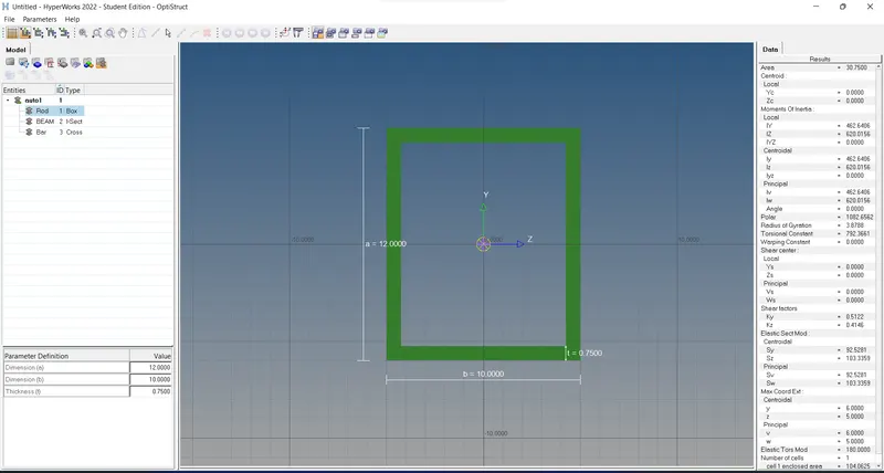
11. After Creating Box Section, Go to Model Browser and Create Property for Rod and Select Beam Section as Box Section.
12. Create a new Component as Rod and assign the Rod Property to the rod component.
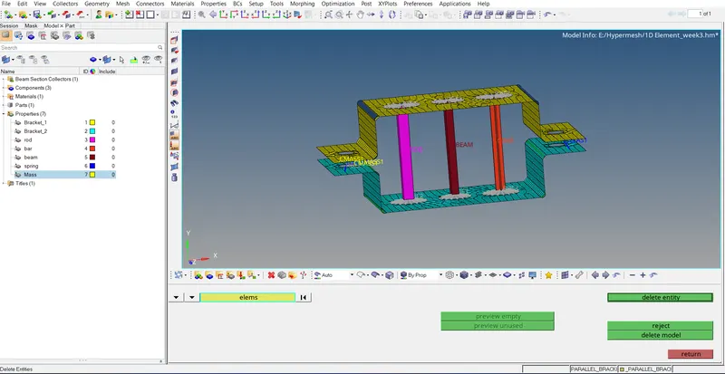
13. Go to 1D-->rods option and Set Property as Rod and element type as CROD and Select Master node of two rigid body and Create it.
2. Beam Element :
14. Creating a Rigid body RBE3 link with all DOF in b.
15. Go to 1D-->rigids option and set as multiple node & calculated node and Select all DOF and select the edges and Click Create.
16. After Creating the RBE3 link, Go to Hyperbeam view-->Create-->Standard Section-->Hypermesh and select type as Standard I Section and Click Create.
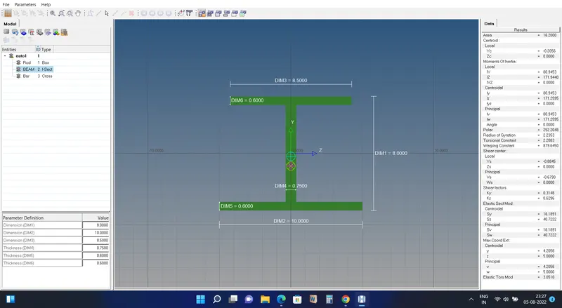
17. After Creating I Section, Go to Model Browser and Create Property for Beam and Select Beam Section as I Section.
18. Create a new Component as Beam and assign the Beam Property to the Beam component.
19. Go to 1D-->bars option and Set Property as beam and element type as CBEAM and Select Master node of two rigid body and Create it.
3. Bar Element :
20. Creating a Rigid body RBE3 link with only x and y DOF in c.
21. Go to 1D-->rigids option and set as multiple node & calculated node and Select only x & Y DOF and select the edges and Click Create.
22. After Creating the RBE3 link, Go to Hyperbeam view-->Create-->Standard Section-->Optistruct and select type as Cross Section and Click Create.
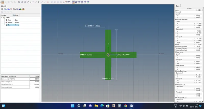
23. After Creating Cross Section, Go to Model Browser and Create Property for Bar and Select Beam Section as Cross Section.
24. Create a new Component as Bar and assign the Bar Property to the Bar component.
25. Go to 1D-->bars option and Set Property as bar and element type as CBar and Select Master node of two rigid body and Create it.
4. Spring Elements :
26. Go to Model Browser and Create Property for Spring, and Select Material as Steel.
27. Create a new Component as Spring and assign the Spring Property to the Spring Element.
28. Go to 1D-->springs option and Select the two nodes of the components and Set elem type as CELAS1 and Create a Spring.