Week 4-1D Element Creation Challenge
AIM :
mesh the Given component with the Size of 5 Units. Create 1D elements on the following component with given cross-section and DOF. Apply the given mass and magnitude at corresponding area.also make spring elements and RBE3,RBE2 connections in proper areas.
OBJECTIVES :
Mesh the Given component with the Size of 5 Units
a. Rod element:- Translational DOF should be Constrained with RBE2 link
Cross-Section: BOX- Dimension a= 12 mm
dimension b=10 mm
Thickness t= 0.75 mm
b. Beam element:- All DOF should be constrained with RBE3 link
Cross-Section: I Section- Dimension a= 8 mm
Dimension b= 10 mm
Dimension c= 8.5 mm
Thickness t1= 0.75 mm
Thickness t2= .6 mm
Thickness t3= .6 mm
c. Bar element:- Constrain only x and y DOFs With RBE3 link
Cross-section: X section- Dimension DIM1= 5 mm
Thickness DIM2= 1.2 mm
Dimension DIM3= 10 mm
Thickness DIM4= 1.2mm
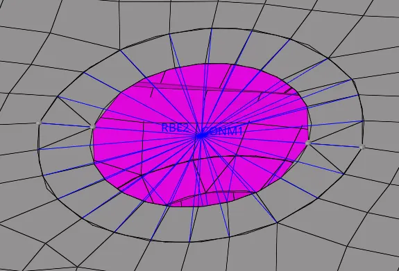
d. & e. Apply the mass of magnitude 10 with the RBE2 link
f. Join the two components with Spring elements
PROCEDURE :
1.open the given parallel bracket by going through import model - import geometry - IGES - select file - import.
2.delete al the lines and unwanted entities displayed on the display by going through delete - elements - displayed - delete entity.
3.then create the midsurface by going through geometry - midsurface -automid surface -select solids - extract.
4.sperately create mid surface component for the paralel bracket and move the upper and lower brackets in to it. for that go to toos - organize - select the midsurfaces - dest component - move.
5.create a steel material bt going through model - create material - steel - create.
6.create proper washer splits on required portions by going through geometry - quick edit - washer spit - off set value - select the circles.
7. for meshing the componenet go to 2D - automesh - apply element size - mesh.
a. rod element
1.create the RBE2 link on the the proper areas that is boath lower and upper brackets by goig through the option, 1D - rigids - select the nodes -apply proper DOF - element type as RBE2 - create.
2.then create a box section in hyper beam by going through model - hyper beam - create - standard section - hypermesh - box section - apply dimensions a , b and t.
3.create a component with suitable name for giving property and material in the model box.
4.then create a rod element between the RBE2 links.for that go to 1D - rods - select nodes - element type - CROD.
5.create a property with suitable name in the model box for applying card image , material and beam section.
6.create the property in the prperty option in horizontal tool bar.for that - go to property - property name - type - 1D -card image -PROD -material - steel - create.
7.assign the property and material for the componenet in model box.
8.assign the card image as PROD,material as steel and beam section as box section in the property created in model box.
9.enable the 1D detailed element representation then the section is appeared.
b.beam element
1.create the RBE3 link on the the proper areas that is boath lower and upper brackets by goig through the option, 1D - RBE3 - select the nodes -apply proper DOF - element type as RBE3 - create.
2.then create a I section beam in hyper beam by going through model - hyper beam - create - standard section - hypermesh - i section - apply dimensions a,b,c,t1,t2,t3.
3.create a component with suitable name for giving property and material in the model box.
4.then create a rod element between the RBE3 links.for that go to 1D - bars - select nodes - element type - CBEAM.
5.create a property with suitable name in the model box for applying card image , material and beam section.
6.create the property in the prperty option in horizontal tool bar.for that - go to property - property name - type - 1D -card image - PBEAM -material - steel - create.
7.assign the property and material for the componenet in model box.
8.assign the card image as PBEAM,material as steel and beam section as I section in the property created in model box.
9.enable the 1D detailed element representation then the I section is appeared.
c.bar element
1.create the RBE3 link on the the proper areas that is boath lower and upper brackets by goig through the option, 1D - RBE3 - select the nodes -apply proper DOF - element type as RBE3 - create.
2.then create a X section in hyper beam by going through model - hyper beam - create - standard section - optistruct - CROSS section - apply dimensions D1M1,D1M2,D1M3,D1M4.
3.create a component with suitable name for giving property and material in the model box.
4.then create a bar element between the RBE3 links.for that go to 1D - bars - select nodes - element type - CBAR.
5.create a property with suitable name in the model box for applying card image , material and beam section.
6.create the property in the prperty option in horizontal tool bar.for that - go to property - property name - type - 1D - card image - CBAR -material - steel - create.
7.assign the property and material for the componenet in model box.
8.assign the card image as CBAR,material as steel and beam section as X section in the property created in model box.
9.enable the 1D detailed element representation then the section is appeared.
d & e.applying mass with RBE2 link
1.make suitable RBE2 links at proper places on the upper and lower brackets.for that go to 1D - rigids - select nodes - element type - RBE2 - create.
2.for applying mass on the created RBE2 link go to , 1D - masses - nodes - apply value - element type - CONM1.
3.apply masses on all the required RBE2 links.
e.join the two componenet with spring element.
1.for joining the components with spring element go to, 1D - springs - select nodes - apply suitable DOF - element type - CELAS1.
2.connect all the required componenets with spring element. 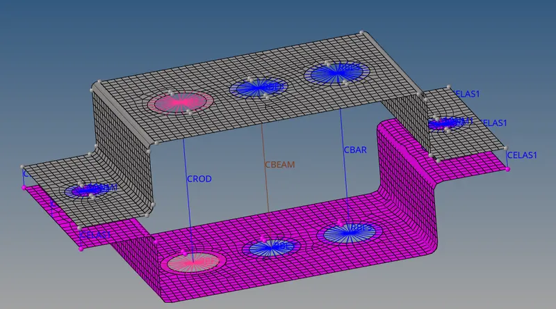
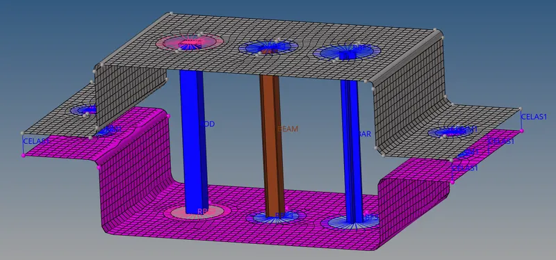
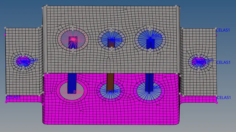
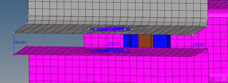
RESULTS :
meshed the Given component with the Size of 5 Units. Created 1D elements on the the given component with given cross-section and DOF. Applied the given mass and magnitude at corresponding areas.also created spring elements and RBE3,RBE2 connections in proper areas.