Week 4-1D Element Creation Challenge
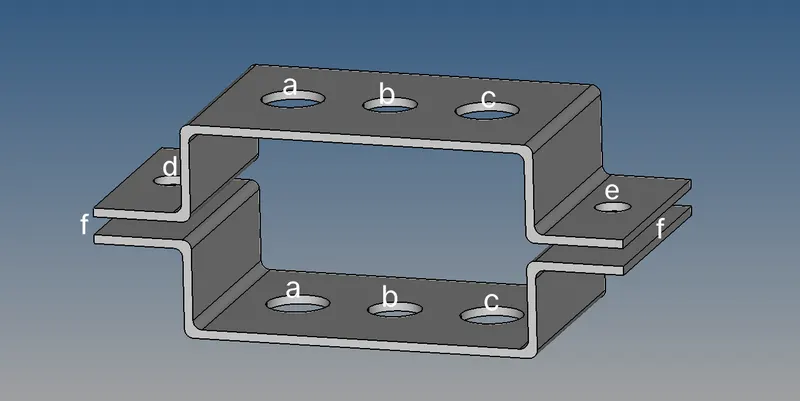
Aim: Mesh the Given component with the Size of 5 Units. Create 1D elements on the following component with the given cross-section and DOF
a. Rod element:- Translational DOF should be Constrained with RBE2 link
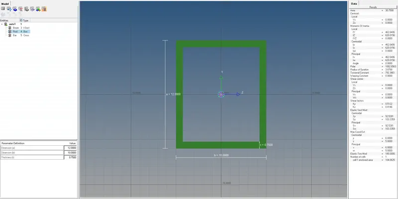
Cross-Section: BOX- Dimension a= 12 mm
dimension b=10 mm
Thickness t= 0.75 mm
b. Beam element:- All DOF should be constrained with RBE3 link
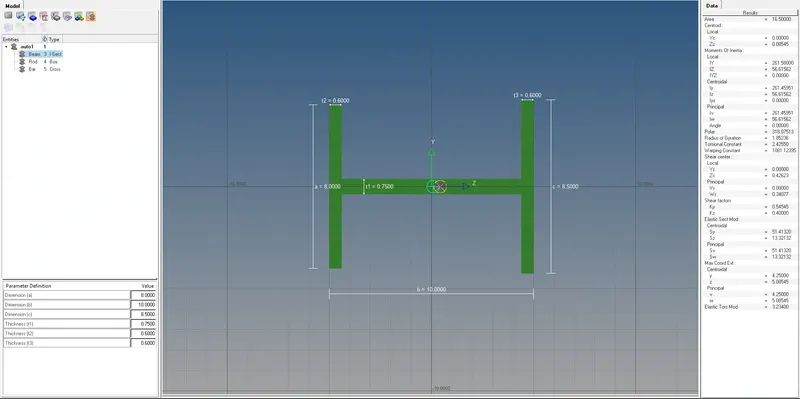
Cross-Section: I Section- Dimension a= 8 mm
Dimension b= 10 mm
Dimension c= 8.5 mm
Thickness t1= 0.75 mm
Thickness t2= .6 mm
Thickness t3= .6 mm
c. Bar element:- Constrain only x and y DOFs With RBE3 link
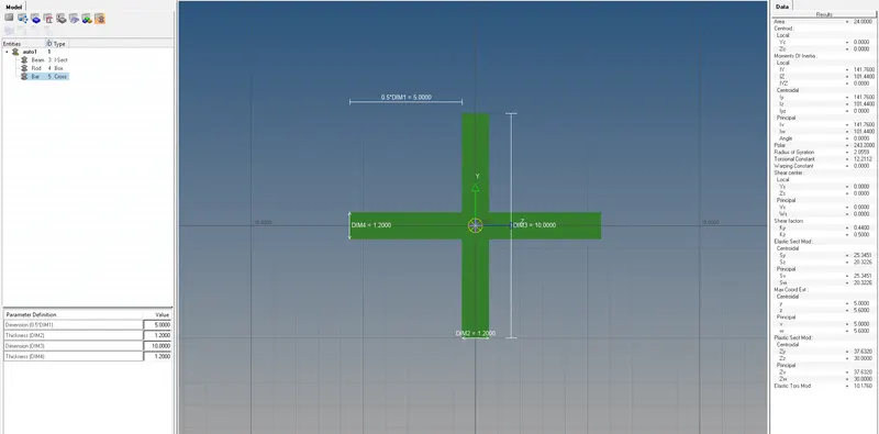
Cross-section: X section- Dimension DIM1= 5 mm
Thickness DIM2= 1.2 mm
Dimension DIM3= 10 mm
Thickness DIM4= 1.2mm
d. & e. Apply the mass of magnitude 10 with the RBE2 link
f. Join the two components with Spring elements
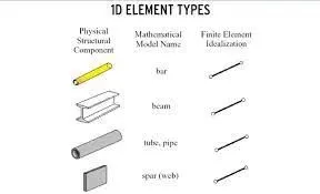
Description: All line elements, whether straight or curved, are called 1D elements with translational and rotational and rotational displacement functions. Examples of the 1D element are the truss element and beam element. 2D elements are typically surface elements with triangle or quadrilateral as their basic shapes.
Procedure:
Import the model by using the geometry option in the form of IGES format
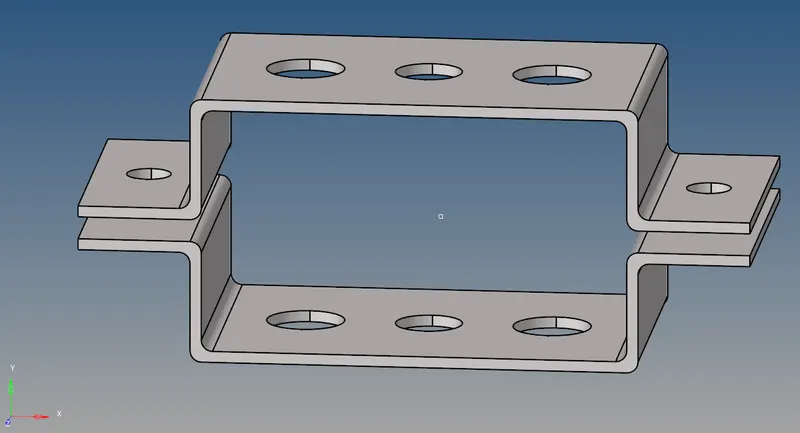
As the thickness of the given component is uniform, the midsurface is taken for the whole model.
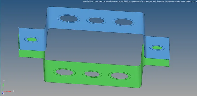
Then we assign the material and properties to the midsurface component in the model browser.
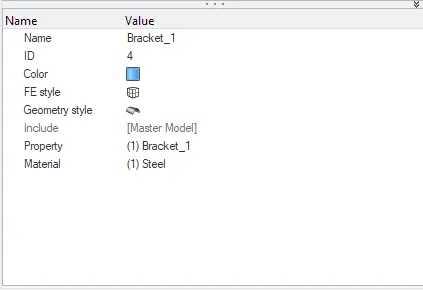
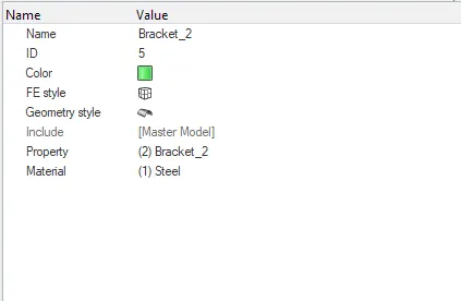
Once material and properties are assigned, we are meshing the component, by using the automesh option in 2D and the target element length should be 8mm, Then we create a washer split surface for the holes.
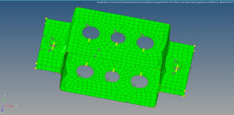
We create RBE2 elements using rigid in 1D module for the first holes on top and bottom and we restrict the element to translational DOF in X, Y and Z axis as mentioned for the first case.
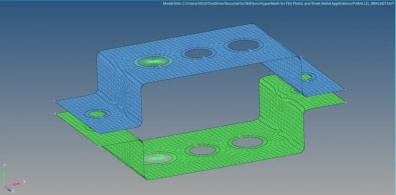
We create RBE3 elements using rigid in 1D module for the first holes on top and bottom and we restrict the element to all DOF in X, Y and Z axis as mentioned for the second case.
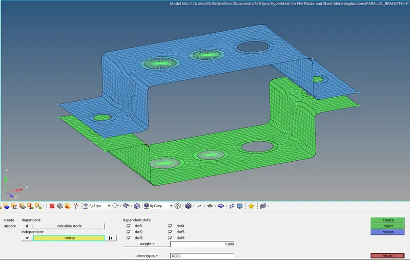
We create RBE3 elements using rigid in 1D module for the first holes on top and bottom and we restrict the element to all DOF in X, Y and Z axis as mentioned for the third case.
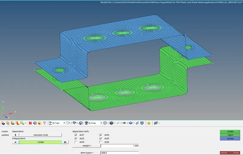
Once RBE2 and RBE3 created, we should create mass with the magnitude of 10 and the type of mass should be given as CMASS1 and we create hyperbeam for rods, bar and beams.
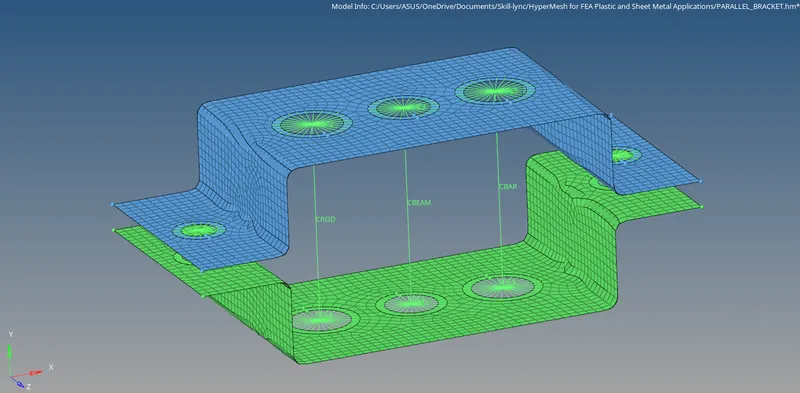
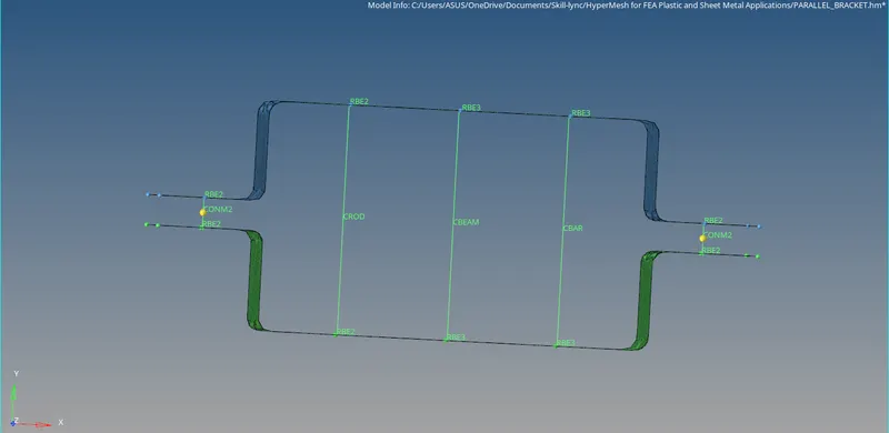
Then we create cross sections for Rod, Bar and Beam
We create cross sections for the rod in the form of thin wall box which has been given for the first case.
We create cross section of the beam in the form of I-section which has been given for the second case.
We create cross sections for the bar in the form of Cross-section which has been given for the third case.
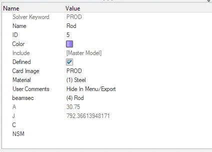
Once cross sections are created, we need to create the property for Rod, Beam, and Bar with property cards such as PROD, PBEAM, and PBAR.
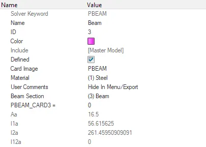
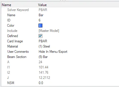
Mass is applied with the magnitude of 10 in RBE2 and spring elements are joined as mentioned.
As we shown all parameters, final result is looks like,
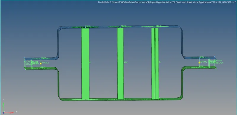
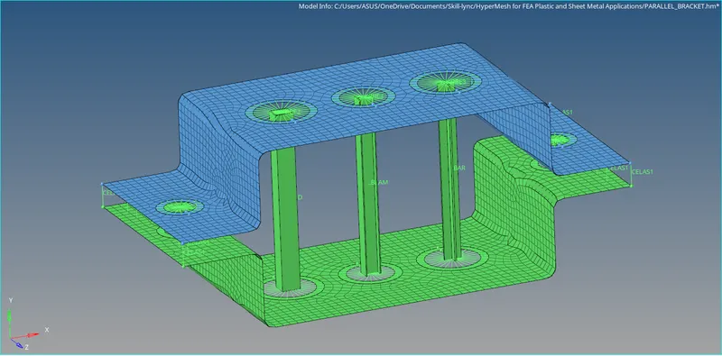
Results:
- The model has been imported and mid-surface is taken for the given components and the material property has been assigned.
- We have meshed the components and Holes has been connected with RBE2 and RBE3 elements.
- Then we created CROD, CBEAM, CBAR 1D elements with their DOF constrained according to the data has been mentioned.
- We create cross section for ROD, BEAM, BAR and Property cards has been assigned for PROD, PBEAM, PBAR.
- The mass has been applied with the magnitude of 10 on mentioned RBE2 and spring elements are joined.