Week 4-1D Element Creation Challenge
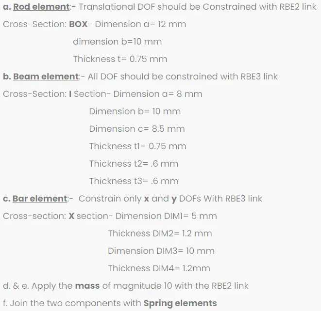
AIM: To mesh the given component with the size of 5 units and also create 1d elements on the following component with the given cross-section and DOF’s as shown below.
Introduction:
While working with 1D elements sooner or later you will come across the following element types:
- CROD - This element “understands” tension and compression loads (axial forces) only. In other words, the nodes of a CROD element only have translation degrees of freedom (still this element has a torsional stiffness).
- CBAR Elements (CBAR & CBEAM) - Simple beams with constant properties (symmetrical and constant cross-section), may be modelled with CBAR or CBEAM elements. However, what you need to recall is that in CBAR elements the origin of the element coordinate system is centered at the shear centre of the cross section (shear centre and neutral axis coincide). Any offsets between the neutral axis and the shear centre are not accounted for. As a consequence, CBAR elements are not useful for modelling beams that warp as it may be the case with open channel sections. This is because, the cross-sections of CBAR elements remain plane. In other words, whenever you are modelling open or nonsymmetric sections be especially cautious with the element type you are going to use.
In brief, CROD elements support (allow) tension and compression only, whereas CBARS and CBEAMS allow bending as well. A CBAR element is a kind of simplified CBEAM element and should be used whenever the cross-section of the structure and its properties is constant and symmetrical. The CBAR element requires that its shear centre and the neutral axis coincide. Due to this requirement CBAR elements are not useful for modelling structures that may warp, such as open channel-sections. This limitation is not present in CBEAM elements. Thus, CBEAM elements are used to model more “complicated” geometries with varying cross sections. Important to note, in CBEAM elements the neutral axis and shear centre are noncoincident. Overall, this type of element demands a deeper understanding of beam theory.
Procedure:
- Let us first import the given model into hypermesh.
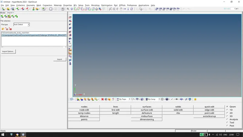
After importing the following is obtained
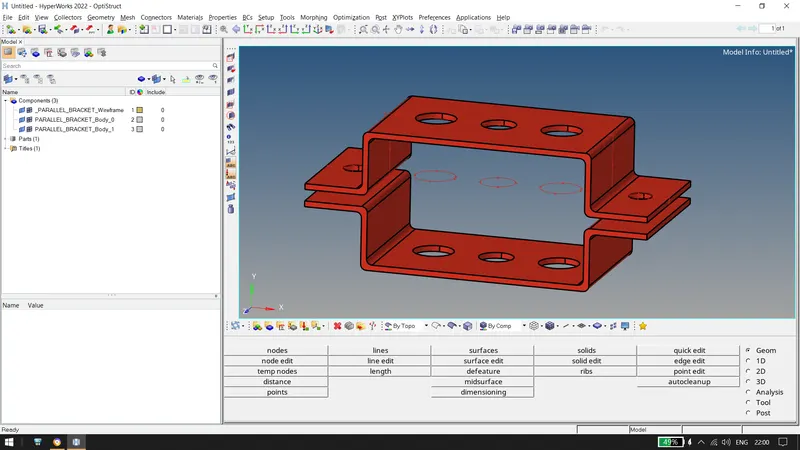
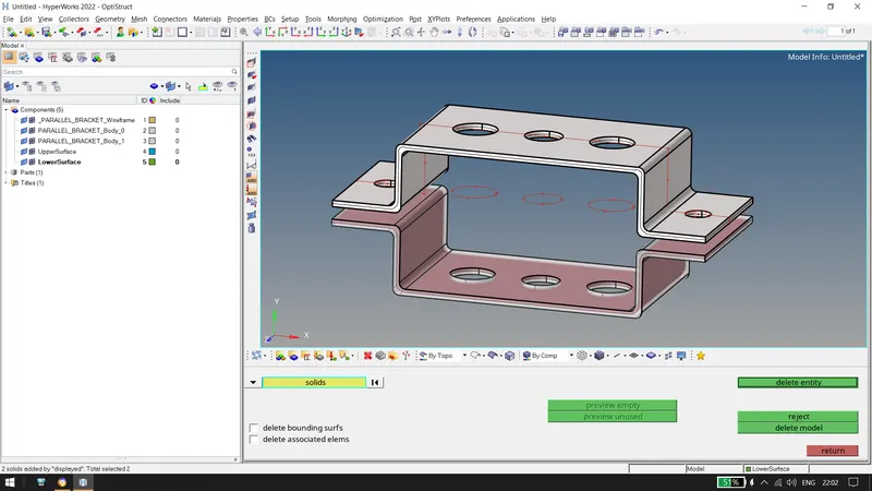
- Now, let us extract the mid surface of PARALLEL BRACKETS creating two different components of the upper and the lower bracket using the midsurface option present in GEOM tab.
 \
\
After creating the midsurface, lets delete the wireframe and the solid of the imported model.
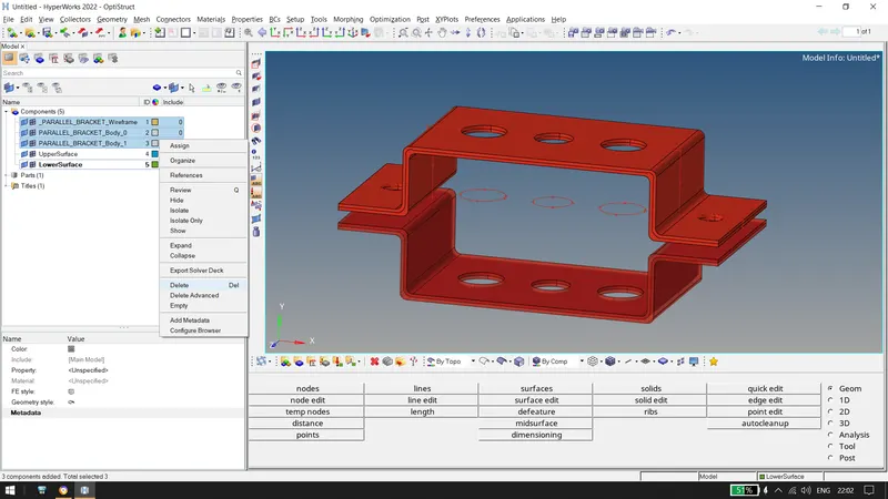
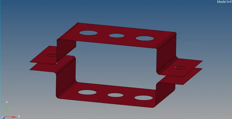
After deleting, the following upper and lower surfaces is obtained as shown below
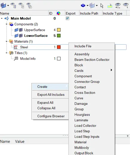
- Now we create a material as steel which is to be assigned to the surface of the bracket.
- Similarily we create two properties to assign to the brackets and assign the material to it.
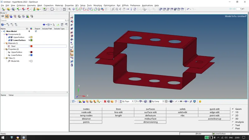
Now Assigning Material to both surfaces:
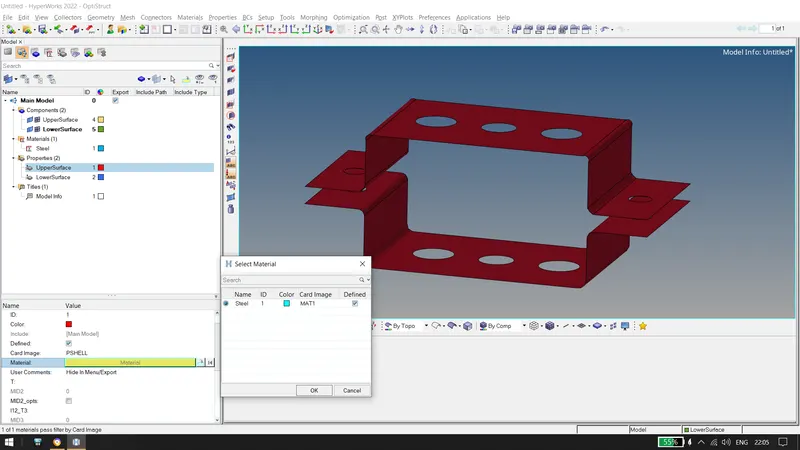
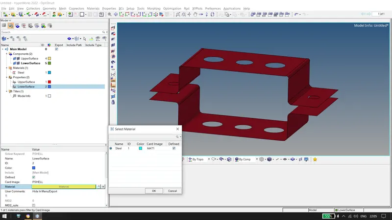
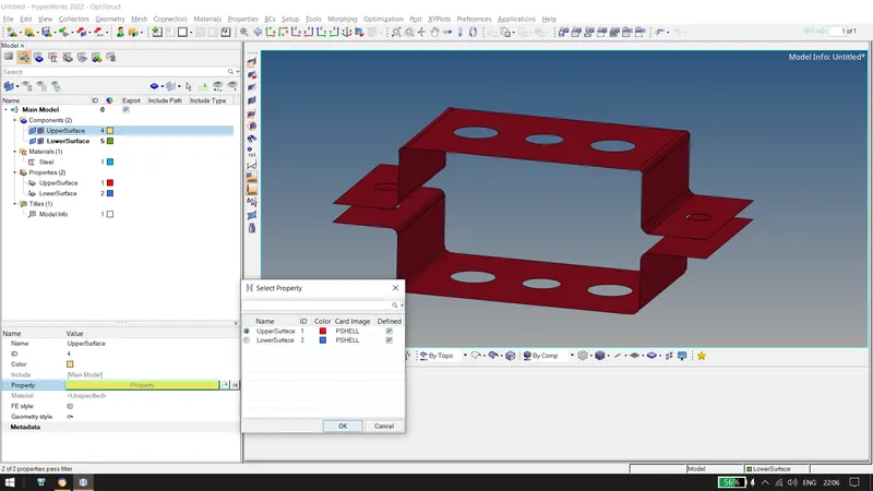
- Again, similarily applying the properties to the components
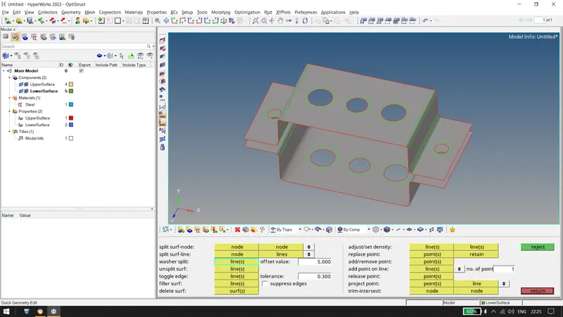
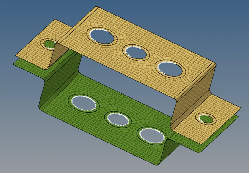
- Now, lets create washer splits with an offset of 5 mm near each and every hole.
- Now, after creating an automesh with an element size of 5, we get the following
- Now, lets create all the RBE2(rigid elements) and RBE3 links as given in the challenge from 1D tab and join them using bars and rods tab with the help of nodes. And we also look at the constraints i.e DOF's given in the challennge.
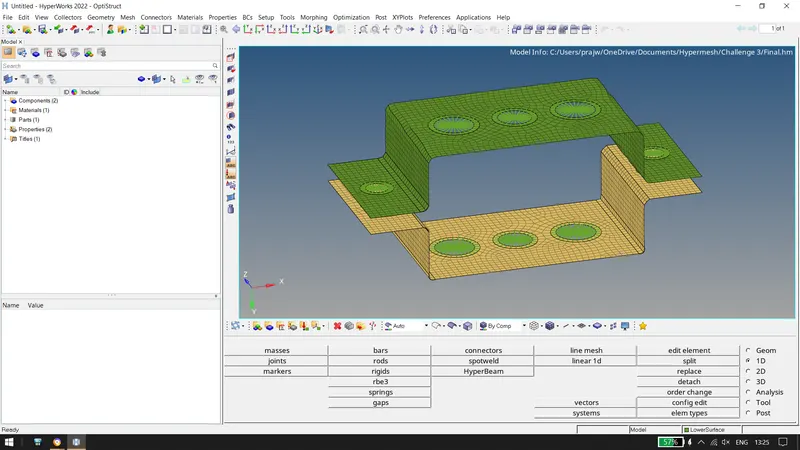
- Creating the given cross sections in the hyperbeam section in 1D tab as shown below.
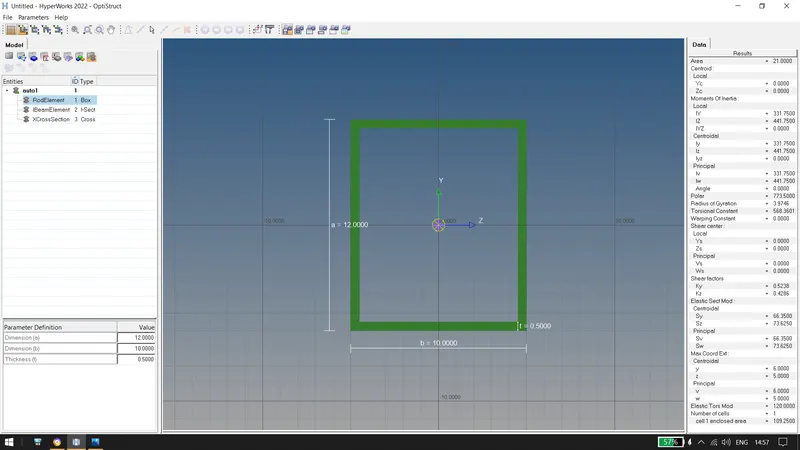
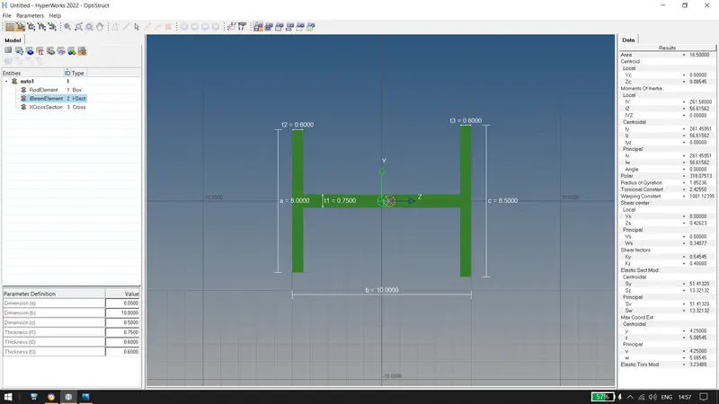
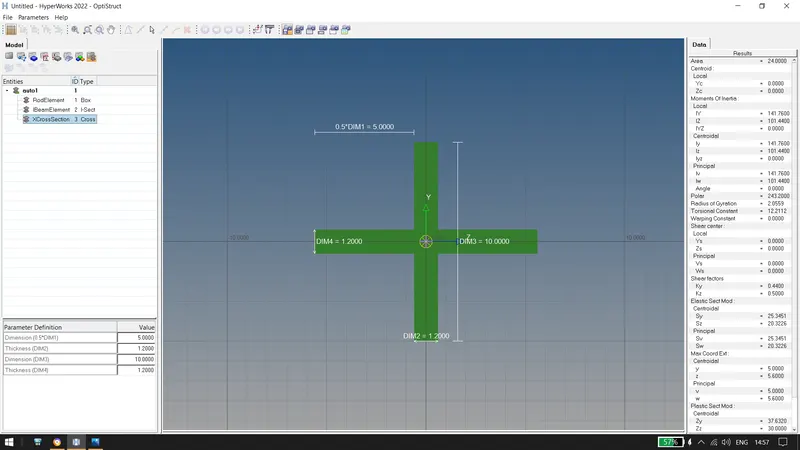
- After creating the rod, beam and bar with given dimension, assigning and updating the cross section to the element created i.e. RBE2 and RBE3 links. Updating the property and element with trespect to their type. For eg. For BAR, element type will be CBAR and property will be bar.
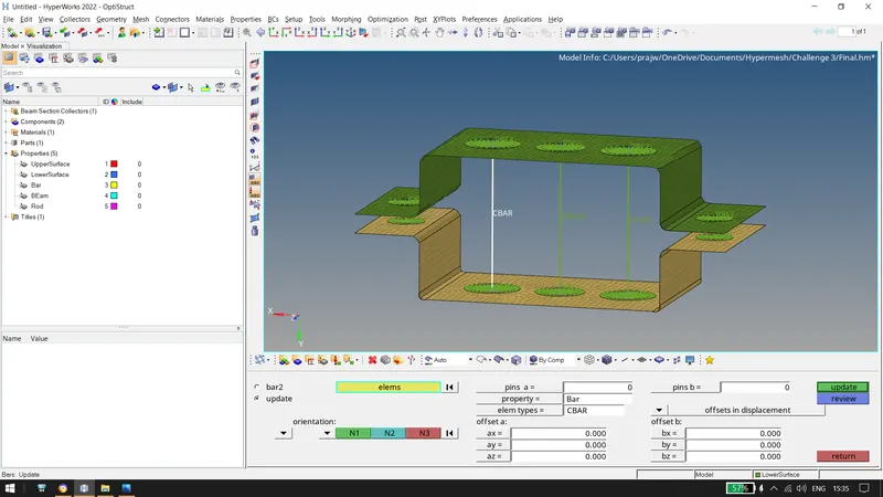
Similarily, we do the same for the other two and get the following.
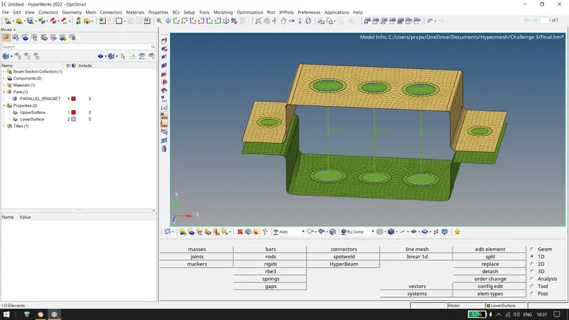
- Turning on the 1d detailed element we get as follows.
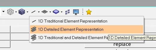
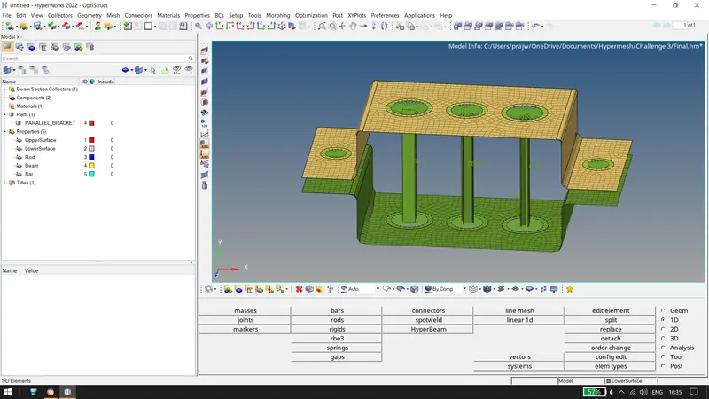
- Now let us add a spring element at d & e as given in the challenge with a mass of magnitude 10. The spring is added in by using springs in 1D tab known as CELAS1 and also mass can be added in the same tab using masses with a magnitude of 10 and specifying the node with the massproperty as CMASS1.
- Hence the final file obtained is as shown below:
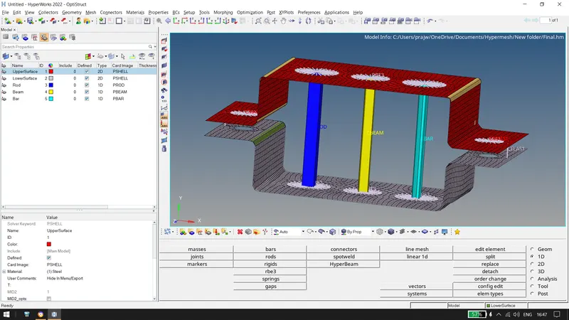
Conclusion: Hence we have successfully meshed the surfaces with an element size of 5 and created the 1D elements with given dimensions. We also learnt how to add materials and assign properties to the surfaces.
The Link for the HM file is https://drive.google.com/file/d/1iHywPHSM9BW22LfnUGzhC4N4ic62KACG/view?usp=sharing