Week 4-1D Element Creation Challenge
Aim:
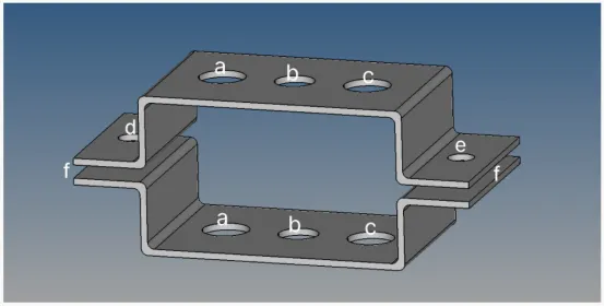
To mesh the Given component with the Size of 5 Units and also to create 1D elements on the following component with given cross-section & DOF
1.Rod element:
- Translational DOF should be Constrained with RBE2 link
- Cross-Section: BOX- Dimension a= 12 mm, b=10 mm, Thickness t= 0.75 mm
2. Beam element:-
- All DOF should be constrained with RBE3 link
- Cross-Section: I Section- Dimension a= 8 mm, b= 10 mm, c= 8.5 mm, Thickness t1= 0.75 mm, t2= .6 mm, t3= .6 mm
3. Bar element:-
- Constrain only x and y DOFs With RBE3 link
- Cross-section: X section- Dimension DIM1= 5 mm, Thickness DIM2= 1.2 mm, Dimension DIM3= 10 mm, Thickness DIM4= 1.2mm
4. d & e. Apply the mass of magnitude 10 with the RBE2 link
5. Join the two components with Spring elements
Procedure:
1. The given model is imported in Hyperworks
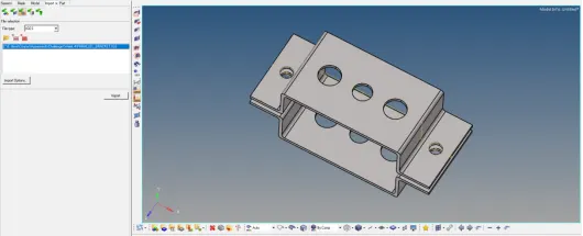
Figure 1 - Imported model
2. Midsurface generation
- For generating midsurface for the given model, select Geometry --> Midsurface --> Auto midsurface --> Auto extraction --> Select surfaces --> Extract
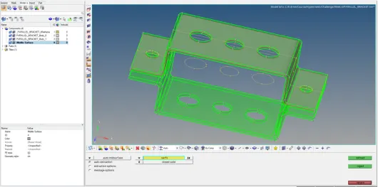
Figure 2 - Mid surface extraction
- The bodies other than the two mid surfaces are deleted from the components in the model browser
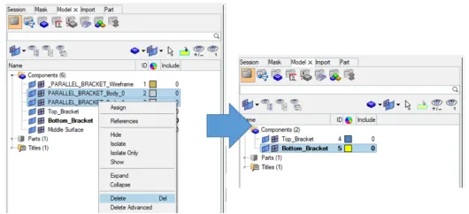
Figure 3 - Delete bodies in model browser
3. Create material for the midsurfaces:
- In the model browser, right click --> Create --> Material
- Enter name as “Steel” in properties and toggle the required properties of the material like young's modulus, density .etc.,
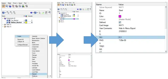
Figure 4 - Create Material
4. Create property and assign material for it:
- In the model browser, right click --> select create --> property. Create two properties for two parts in the model
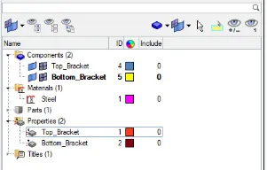
Figure 5 - Create Property
- Enter thickness of each property in the property card and assign material as steel
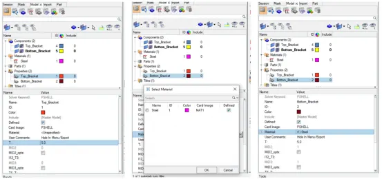
Figure 6 - Enter property thickness and assign material
- Link property to components
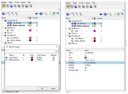
Figure 7 - Link property to components
5. Add washer split
- To add washer split, select Geometry --> Quick edit --> Washer split --> Enter offset distance --> Select lines to generate washer split
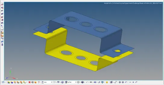
Figure 8 - Adding washer split
6. Meshing
- Select 2D --> Automesh --> Enter element size as 5 --> Mesh type as mixed --> select the surfaces to mesh --> Select mesh
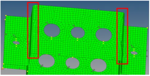
Figure 9 - Meshing
- After first meshing, it is observed that the meshing in the edges shown in the above picture, is not proper. So, lines are created on the filleted edges. Using the trim with lines option in Geometry --> Surface edit, created lines are used to create edges on the surface
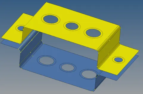
Figure 10 - Create edges
- Meshing is done again and it is observed that the edges are meshed proper
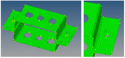
Figure 11 - Proper mesh
7. Beam section creation:
- Select 1D --> Hyperbeam --> select section library as Hyperbeam --> select standard section type as thin walled box --> click create
- The hyperbeam window opens
- In the hyperbeam, enter the given parameters for Rod element
- The beam section is created and is named as Rod
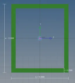
Figure 12 - Box beam section
- Similarly, the other two sections are created in the same hyperbeam window
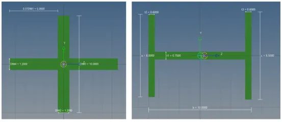
Figure 13 - Cross and I Beam sections
8. Assign property for the created beam sections:
- In the properties tab, create new property for all the beam sections
- In the property card,
- Select card Image as PROD for rod element, PBEAM for beam element & PBAR for bar element
- In the beam section assign the appropriate beam section
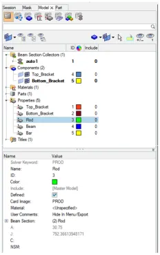
Figure 14 - Create and assign property for Beam sections
9. 1D elements creation:
- RBE2:
- Select 1D --> Rigids --> Create --> select multiple nodes --> select calculate node --> As per the given task, translational nodes should be constrained. So, the rotational nodes (dof4, dof5, dof6) are unchecked --> Select nodes --> Create
- RBE3:
- Select 1D --> RBE3 --> Create --> select nodes --> select the dofs to be unconstrained --> Create
- Springs:
- Select 1D --> Springs --> Create --> Select the nodess to connect --> select element type as CELAS1
- Mass:
- Select 1D --> Masses --> Create --> select the node --> Enter mass --> Set element type as CMASS1 --> Create
- Rod:
- Select 1D --> Rods --> Create --> Select nodes --> Select property as Rod & Element type as CROD --> Create
- Bars:
- Select 1D --> Bars --> Select the nodes to connect --> Select orientation --> Select property as Bar & Element type as CBAR --> press Tab to create
- Similarly for Beams, the steps are repeated. But the property is selected as Beam and element type as CBEAM --> press Tab to create
- The created model is as follows:
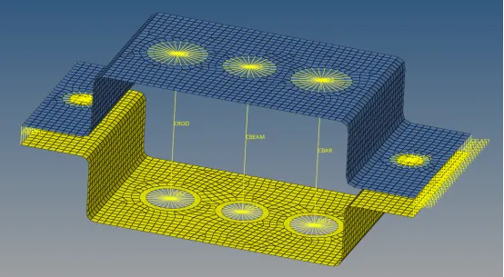
Figure 15 - Meshed model with 1D elements
- The model can be toggled to detailed representation by using the 1D & 2D Detailed Element Representation
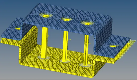
Figure 16 - Final model
Learning Outcomes:
- Midsurface creation for given component
- Create mesh
- Create 1D bar, rods, rigids, RBE3 and spring elements
Conclusion:
The Given component is meshed with the Size of 5 Units and also 1D elements on the component with given cross-section & DOF is created