Week 4-1D Element Creation Challenge
Meshing and Creating 1D Element by Using Hyperworks - Optistruct solver
AIM:
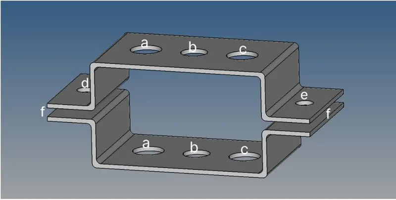
The main objective of the Challenge is to mesh the given component called Bracket with a target length of 5mm and to make the 1D elements like Rod, Beam, and Bar with the given cross-section and D.O.F(Degrees of freedom) by using the Hypermesh software.
GIVEN DATA:
a)Rod Element:
- Translational DOF should be constrained with RBE2 link
- Cross-section: Box
- Dimension, a=12mm
- Dimension, b=10mm
- Thickness, t=0.75mm
b)Beam Element:
- All DOF should be constrained with the RBE3 link
- Cross-section: I-section
- Dimension, a=8mm
- Dimension, b=10mm
- Dimension, c=8.5mm
- Thickness, t1=0.75mm
- Thickness, t2=0.60mm
- Thickness, t3=0.60mm
c)Bar Element:
- Constrain only X and Y DOF with RBE3 link
- Cross-section: X-section
- Dimension, DIM1=5mm
- Dimension, DIM2=1.2mm
- Dimension, DIM3=10mm
- Dimension, DIM4=1.2mm
d&e)Apply the mass of magnitude 10 with the RBE2 link:
f)Join the components with spring Elements:
PROCEDURE:
1. Import the Model:
The HyperWorks offers various options for importing and exporting any model the options present in the import and export menu are the same. The following option is present,
- Import Model
- Import Solver Deck
- Import Geometry
- Import BOM
- Import Connectors
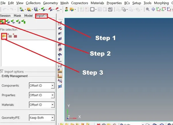
The following steps are present in the TAB area,
- Import >>> Import Model >>> Select files
2. Mid-surfacing:
Mid-surfacing modeling is a technique for creating a simplified shell representation of a solid model. It can reduce the computational expense of analyzing a complete solid when a shell mode with a defined thickness and fewer details is suitable for the required analysis.
steps for midsurfacing
3. Meshing:
Meshing is a part of the simulation process where complex geometries are divided into simple elements that can be used as discrete local approximations of the larger domain. The mesh influences the accuracy, convergence, and speed of the simulation.
- Automesh option is used for meshing a surface with 2D elements
- Change Geom mode as 2D in the Mainmenu bar
- Then select the Automesh option
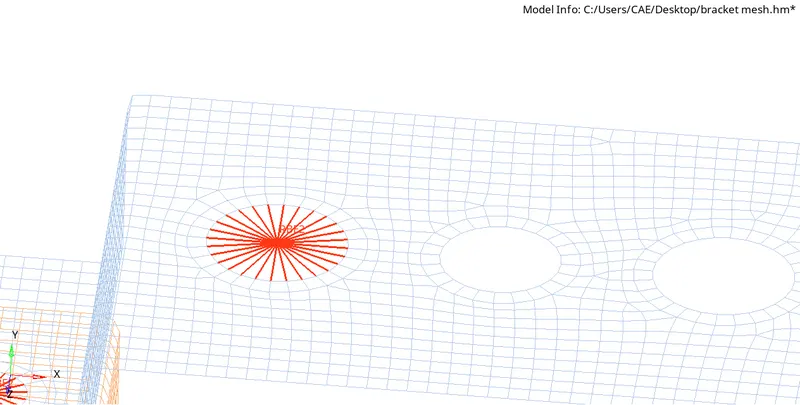
after meshing it is required to make 1D element connection
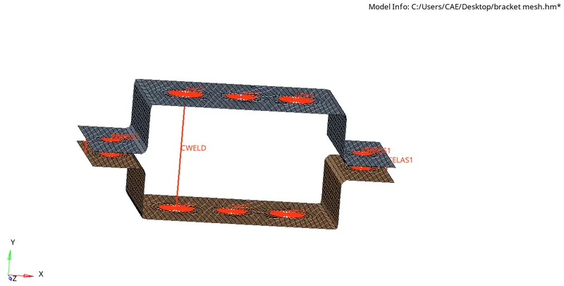
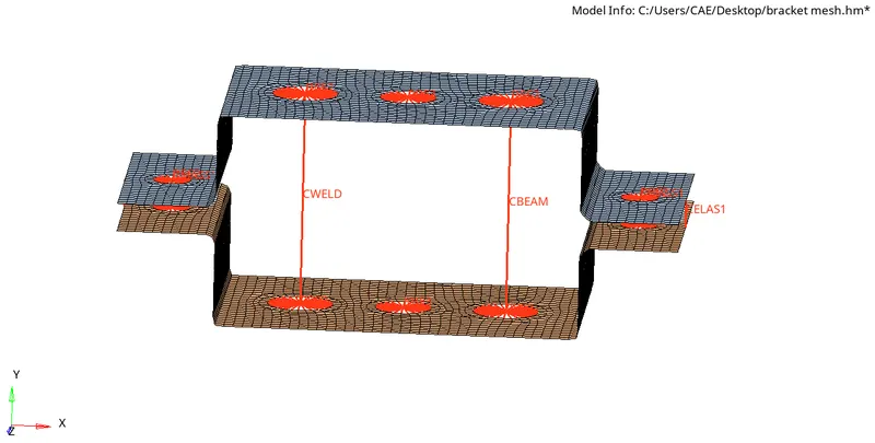
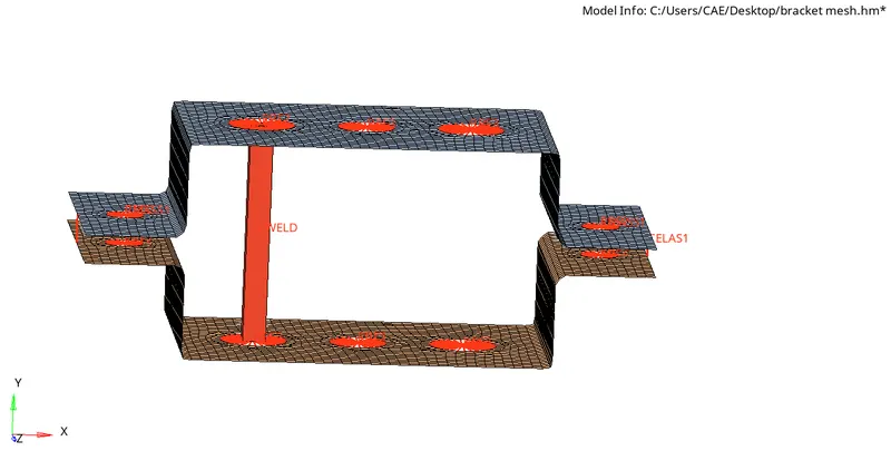
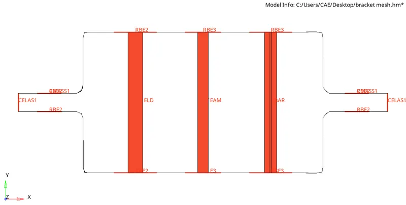
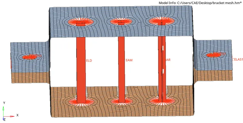
RESULT:
The Given parallel bracket has meshed with an element length of 5mm and the 1D elements have been created as per the reference and also the Cross-section and DOF has been assigned properly.