Week 4-1D Element Creation Challenge
AIM:
To Mesh the Given component with the Size of 5 Units. Create 1D elements on the following component with given cross-section and DOF.
OBJECTIVE:
To determine the following:
a. Rod element:- Translational DOF should be Constrained with RBE2 link
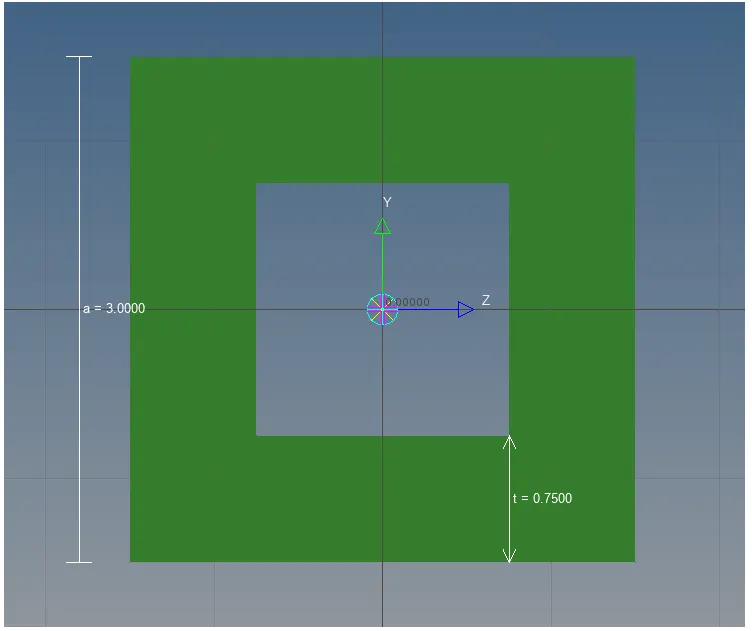
Cross-Section: BOX- Dimension a= 12 mm
dimension b=10 mm
Thickness t= 0.75 mm
b. Beam element:- All DOF should be constrained with RBE3 link
Cross-Section: I Section- Dimension a= 8 mm
Dimension b= 10 mm
Dimension c= 8.5 mm
Thickness t1= 0.75 mm
Thickness t2= .6 mm
Thickness t3= .6 mm
c. Bar element:- Constrain only x and y DOFs With RBE3 link
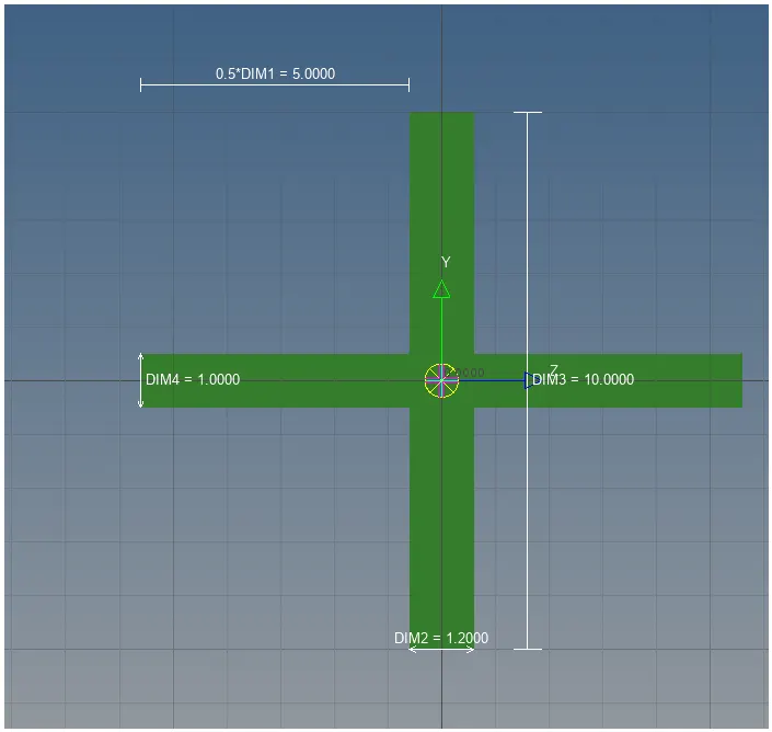
Cross-section: X section- Dimension DIM1= 5 mm
Thickness DIM2= 1.2 mm
Dimension DIM3= 10 mm
Thickness DIM4= 1.2mm
d. & e. Apply the mass of magnitude 10 with the RBE2 link
f. Join the two components with Spring elements
THEORY:
Rod is a linear element type with a circular cross-section.
Bar can have any shape of the cross-section.
Beam is a type of bar but it can have any loads such as axial, bending and shear loads and also moments and torque loads.
A rigid element is used to rigidly connect two nodes of a model or to transfer an external load on to the model.
RBE-2:
RBE2 elements add infinite stiffness to the nodes being constrained.
RBE-3:
RBE3 elements provide a distributed connection which does not influence the local stiffness of the model.
PROCEDURE:
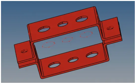
1.Importing The Geometry:
i.Click on the import from the main menu bar and select import geometry.
ii.Click on the import then the geometry appears on the display.
iii.The geometry imported appear.
2.Extract mid surface from the two brackets and name them upper and lower body:
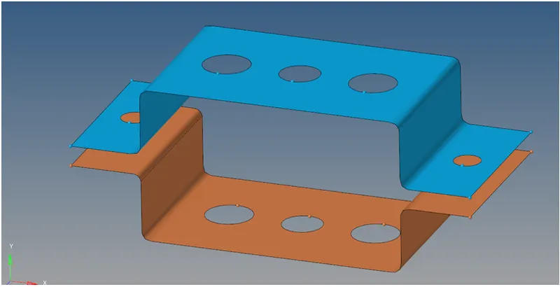
i.Click on the geometry in the menu bar.
ii.Click on the mid-surface.
iii.Click on the surface and select the upper bracket and name it as bracket-1.
iv.Similarly do it for the other bracket and name it as bracket-2.
v.The mid-surfaces created.
3.Apply washer splits with offset of 5mm:
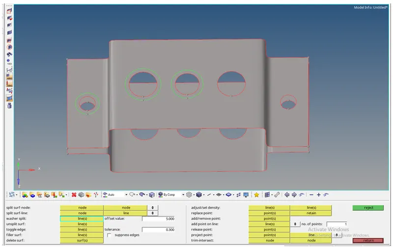
i.Click on the quick edit in the geometry menu bar.
ii.Click on the washer split and select the circular sections on the geometry.
iii.Then the geometry appears.
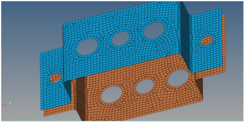
4.Apply 2D AutoMesh with element size 5:
i.Click on the 2D from the menu bar.
ii.Click on the auto mesh and enter the element size as 5 and select the mesh type as quad.
iii.Click create and the mesh forms on the geometry surface.
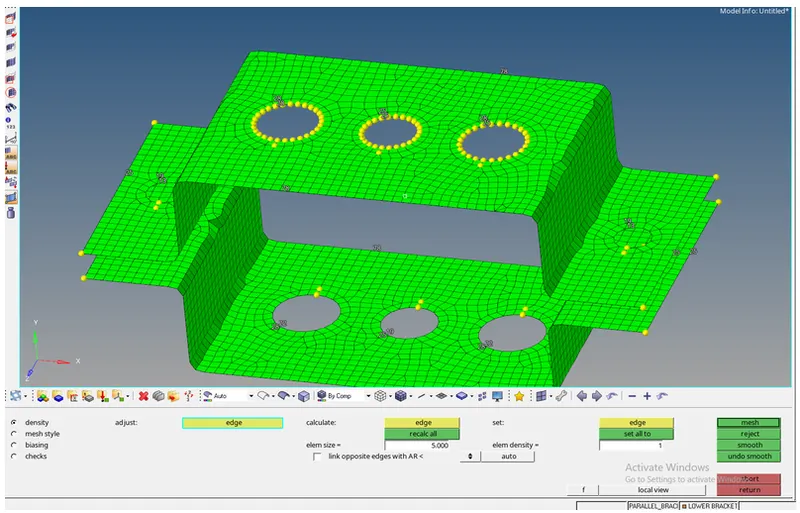
5.Fixed the holes accordingly to create a fine mesh to be then used for carrying out the rigid elements:
6.Creating a material and properties for the two brackets:
i.On the tab bar give the right click.
ii.Click on the create and select property.
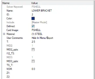
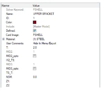
iii.Create the properties and assign them the specific type of material and other details like thickness.
iv.Right click on the tab bar and select create.
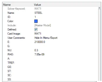
v.Create material and specify it as steel.
I.Material:
II.Lower Bracket Property:
III.Upper Bracket Property:
7.Apply RBE2 elements to holes marked with "a" and translational DOF constrained:
i.Click on the 1D from the menu bar.
ii.Select the rigids on the menu set element type to RBE2.
iii.Select the circular nodes and create the RBE2.
iv.Click on the rods in the 1D menu and select nodes of the RBE2 links.
v.Constrain the degrees of freedom for translational.
vi.Click on the create and the rod appears on the screen between the RBE2 links.
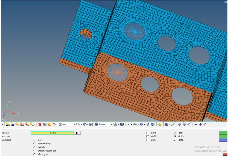
8.Apply RBE3 elements to holes marked with "b" and "c" with all DOF and X,Y are constrained respectively:
i.Click on the 1D from the menu ba.
ii.Select the rigids on the menu set element type to RBE3.
iii.Click on the bars and select the nodes click on create and select the element type as CBeam.
iv.Constrain the degrees of freedom.
v.Click on the create now we can see the beam element created between the RBE3 nodes.
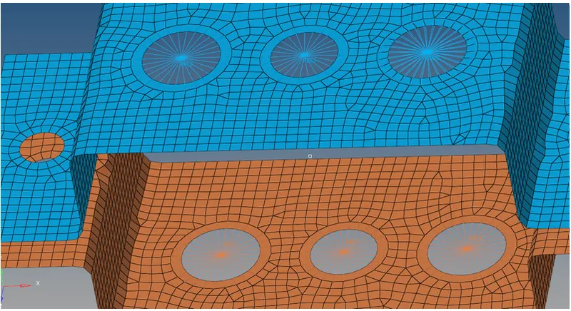
9.Create a cross-section for Rod, Beam and Bar in HyperBeam:
I.Beam:
Dimensions Given:
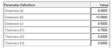
Figure:
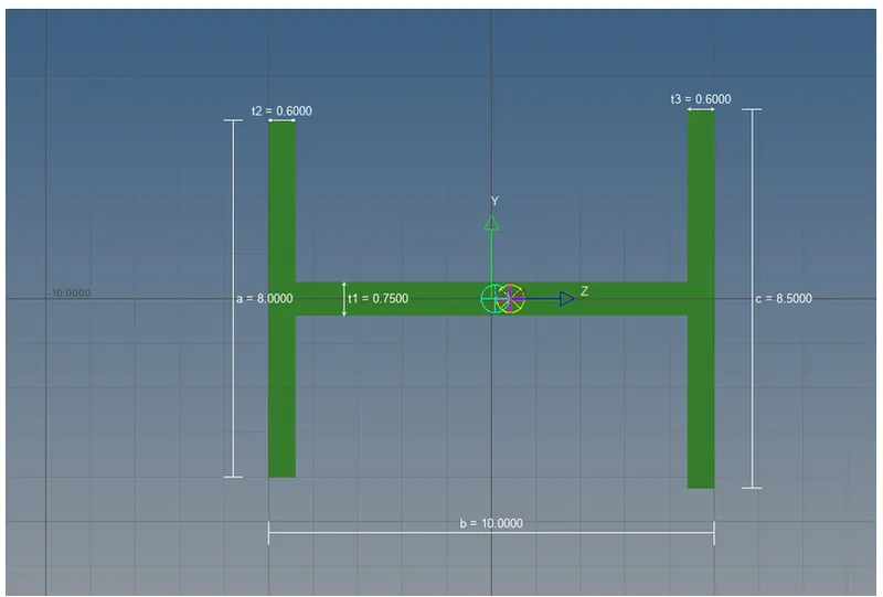
II.Rod:
Dimensions Given:
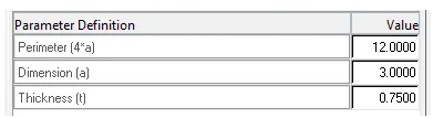
Figure:
III.Bar:
Dimensions Given:
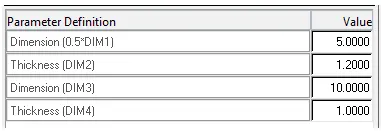
Figure:
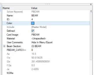
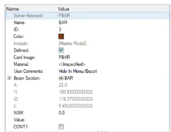
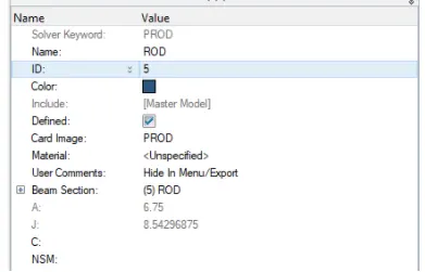
10.Create properties for beam, bar and rod by changing card image and beam section as follows:
I.Beam:
II.Bar:
III.Rod:
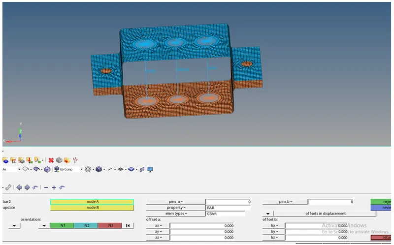
11.Using Rod and Bar from 1D menu bar create Rod, Beam and Bar with their respective properties.
I.BAR:
II.BEAM:

III.ROD:
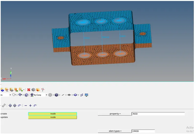
12.Create mass of 10 magnitude of "d" and "e" hole respectively. But before that RBE2 element should be present there to carry out the load.
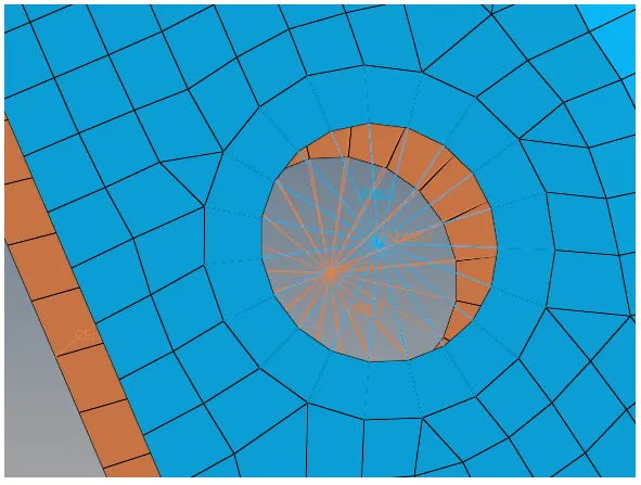
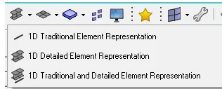
13.Applying the spring element with CELAS1 element type with default properties and use the corner nodes to attach. To get a detailed representation of 1D element in 3D use 1D detailed elemental representaiton mode.
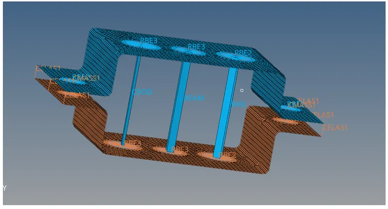
OBSERVATION:
Thus the given challenge is determined sucessfully.
RESULT:
Thus the Mesh the Given component with the Size of 5 Units. Create 1D elements on the following component with given cross-section and DOF is created sucessfully.