Week 4-1D Element Creation Challenge
Week 4 - 1D Element Creation Challenge
Objective : Mesh and Create 1D elements on the following component with given cross-section and DOF.
Given model image :
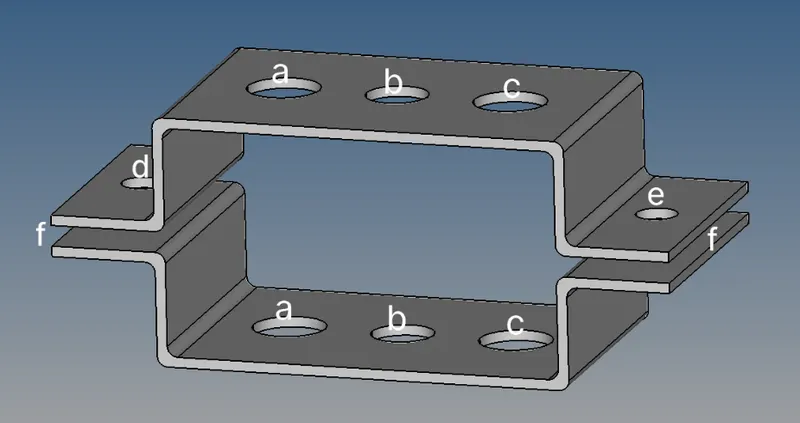
Given cross section and DOF :
-
Rod element :- Translational DOF should be Constrained with RBE2 link.
Cross-Section: BOX a= 12 mm, b=10 mm and thickness t= 0.75 mm
-
Beam element :- All DOF should be constrained with RBE3 link
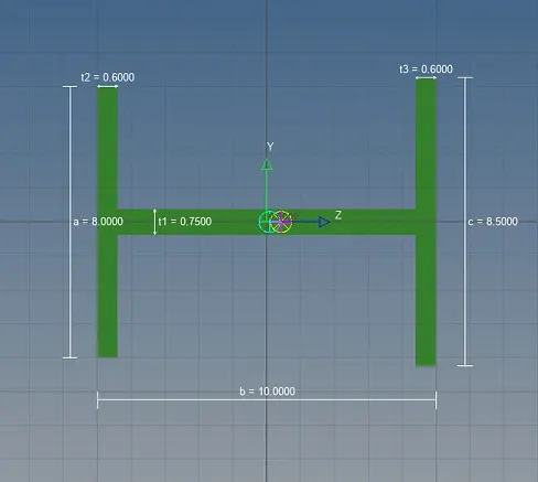
Cross-Section: I-Section a= 8 mm, b= 10 mm, c= 8.5 mm, thickness t1= 0.75 mm, t2= 0.6 mm and t3= 0.6 mm
-
Bar element :- Constrain only x and y DOFs With RBE3 link
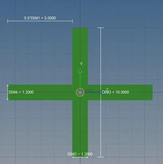
Cross-section: X-section DIM1= 5 mm, DIM2= 1.2 mm, DIM3= 10 mm, DIM4= 1.2mm
-
Apply the mass of magnitude 10 with the RBE2 link
- Apply the mass of magnitude 10 with the RBE2 link
f. Join the two components with Spring elements.
Procedure :
A) Import the geometry
- Click on the import from the main menu bar and select import geometry.
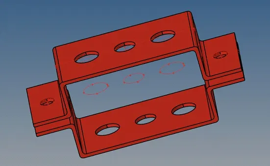
- Click on the import then the geometry appears on the display.
- The geometry imported appear as follows.
B) Create mid-surface
- Click on the geometry in the menu bar.
- Click on the mid-surface.
- Click on the surface and select the upper bracket and name it as bracket-1
- Similarly do it for the other bracket and name it as bracket-2.
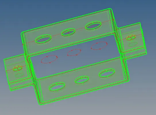
- The mid-surfaces created appear as follows.
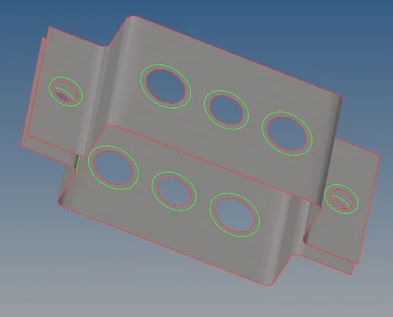
C) Create washer split on the geometry surface
- Click on the quick edit in the geometry menu bar.
- Click on the washer split and select the circular sections on the geometry.
- The geometry appear as follows.
D) Create meshing on surface
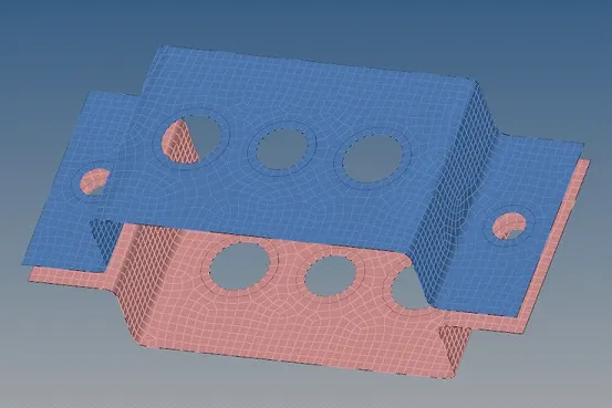
- Click on the 2D from the menu bar.
- Click on the automesh and enter the element size as 5 and select the mesh type as quad.
- Click create and the mesh forms on the geometry surface. It appears as follows.
E) Create properties and materials
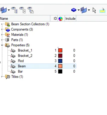
- On the tab bar give the right click.
- Click on the create and select property.
- Create the properties and assign them the specific type of material and other details like thickness.
- Right click on the tab bar and select create.
- Create material and specify it as steel.
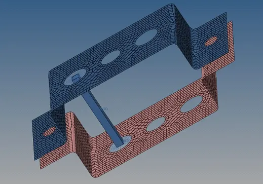
F) Create Rod element :
1) Translational DOF should be Constrained with RBE2 link
- Click on the 1D from the menu bar.
- Select the rigids on the menuSet element type to Rbe2.
- Select the circular nodes and create the Rbe2 as shown.
- Click on the rods in the 1D menu and select nodes of the Rbe2 links.
- Constrain the degrees of freedom for translational.
- Click on the create and now the rod appears on the screen between the Rbe2 links.

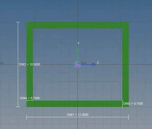
2) Cross section : Box
- Click on the hyperbeam in the 1D menu bar.
- Click on the standard section,select the optistruct and in element section select the BOX.
- Click on create,will be redirected to the hyperbeam view mode.
- The box will be created and seen.
- Enter the dimensions as, a= 12 mm, b=10 mm and thickness t= 0.75 mm.
3) Creating box section on the rod element
- Click on the model view and click on the rods in the 1D menu.
- Click on the rod property created in the tab bar and enter the card image as Prod.
- Specify the material type as steel,and beam section as Box created in the hyperbeam.
- Click on the rods in the 1d geometry and select update.
- Give the update properties i.e. box.
- In the menu bar select the 1D element representation,the box can be seen.
G) Create Beam element :
1) All DOF should be constrained with RBE3 link
- Click on the Rbe3 in the 1D menu.
- Click on the nodes and create the Rbe3 on the top and bottom brackets.
- Click on the bars and select the nodes,click on create and select the element type as CBeam.
- Constrain all the degrees of freedom.
- Click on create,now you can see the beam element created between the Rbe3 nodes.

2) Cross section : I-section
- Click on the hyperbeam view.
- Click on the standard section and select the element type as I section.
- Click on create,will be redirected to the hyperbeam view.
- Click on the I section rename it as beam and give the dimensions as prescribed,
- a= 8 mm, b= 10 mm, c= 8.5 mm, thickness t1= 0.75 mm, t2= 0.6 mm and t3= 0.6 mm.
3) Create I section on the beam element
- Click on the model view and update the property of beam for material as steel.
- Card image has to be set for Pbeam and beam section as beam.
- Click on bars in the 1D menu.
- Click on update and select the element type as beam,property as beam and click on update.
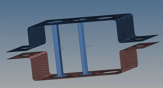
- Click on the 1D element detailed representation.
H) Create Bar element :
1) Constrain only x and y DOFs with RBE3 link
- Click on the Rbe3 in the 1D menu.
- Click on the nodes and create the Rbe3 on the top and bottom brackets.
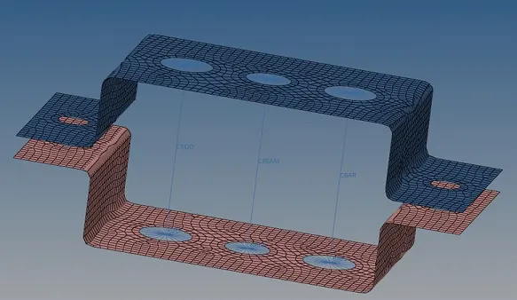
- Click on the bars and select the nodes,click on create and select the element type as CBar.
- Constrain the degrees of freedom for only x,y .
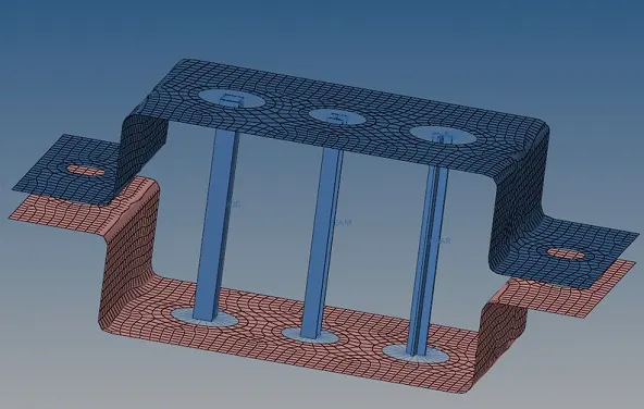
- Click on create,now you can see the bar element created between the Rbe3 nodes.
2) Cross section : X - section
- Click on the hyperbeam view.
- Click on the standard section and select the element type as cross(X) section.
- Click on create,will be redirected to the hyperbeam view.
- Click on the X section rename it as bar and give the dimensions prescribed.
- DIM1= 5 mm, DIM2= 1.2 mm, DIM3= 10 mm, DIM4= 1.2mm.
3) Create X section on bar element
- Click on the model view and update the property of bar for material as steel.
- Card image has to be set for Pbar and bar section as bar.
- Click on bars in the 1D menu.
- Click on update and select the element type as bar,property as bar and click on update.
- Click on the 1D element detailed representation.
I) Apply the mass of magnitude 10 with the RBE2 link
- Click on the 1d menu and select the rigids and create the nodes create the rbe2 link on the d,e holes of the brackets.
- Click on the masses from the 1D menu.
- Enter the mass value as 10, mass type as Cmass1 ,select the Rbe2 links either sides click on apply.
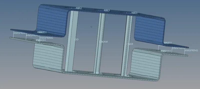
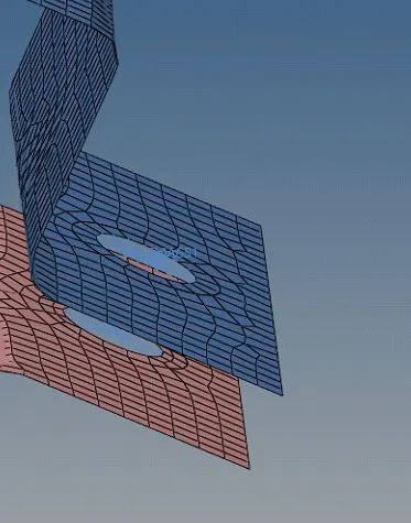
- You can see the masses created at the Rbe2 links as below.
J) Join the two components with Spring elements
- Click on the 1D in the menu bar.
- Click on the springs.
- Select the nodes at the either edges of the bracket and select the element type as HMspring.
- Click on create , do it at the both edges of the brackets, result will be as shown in image.
Final model image :
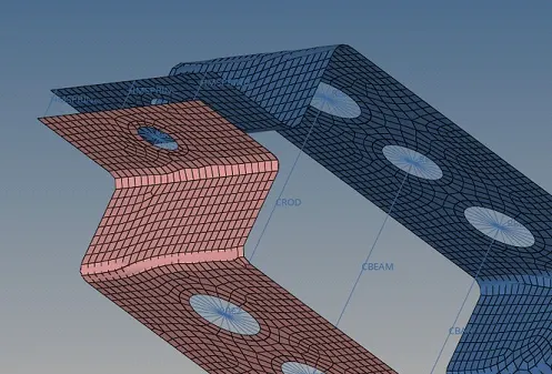
This is the final output of all the tasks, click on 1D Detailed Element Representation.