Week 4-1D Element Creation Challenge
1. Extract the model by selecting File-import geometry-PARALLEL_BRACKET.IGES file.
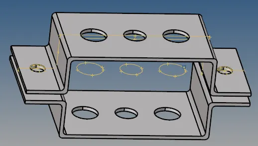
2. Extract the midsurfaces by slecting Geom-midsurfaces, keep automidsurface option and select the top bracket and click extract. Rename it as Bracket 1. Similarly create the second midsurface.
3. Now create a new component Bracket 2. Movve the second midsurface to this by selecting Tool-organize- select the destination as Bracket 2 and click on the second midsurface. Give colour to Bracket 1 and Bracket 2.
4. Now delete PARALLEL_BRACKET_Body_0, PARALLEL_BRACKET_Body_1 and hide _PARALLEL_BRACKET_Wireframe. Now only the midsurfaces are visible.
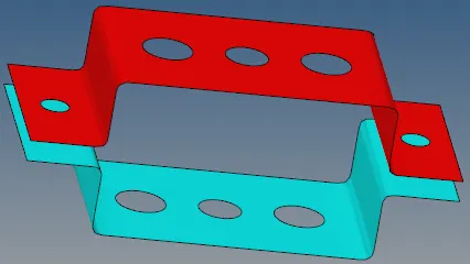
5. Create components- compoent 1, component 11 and component 111 for rod, beam and bar respectively.
6. Create properties Bracket 1, Bracket 2, Rod, Beam and Bar. For Bracket 1 and Bracket 2 keep Card Image as PSHELL, for Rod as PROD, for Beam as PBEAM and for bar as PBAR.
7. Create material steel and assign to all the properties.
8. Creater washer split for all circles with offset of 4.
9. Mesh the component by selecting 2D-automesh, select element size as 5 and click mesh.
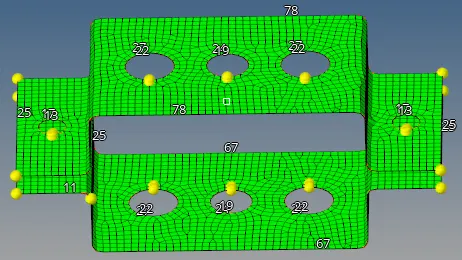
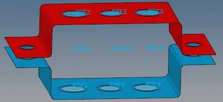
10. To create the rold element first create RBE2 links. Select 1D-rods-select nodes on the RBE2 links, keep element type as CROD.
11. To create the beam element first create RBE3 links. Select 1D-bar-select nodes on the RBE3 links, keep element type as CBEAM and give appropriate orientation.
12. To create the bar element first create RBE3 links. Uncheck dof4 and dof6. Select 1D-bar-select nodes on the RBE3 links, keep element type as CBAR and gvie appropriate orientation.
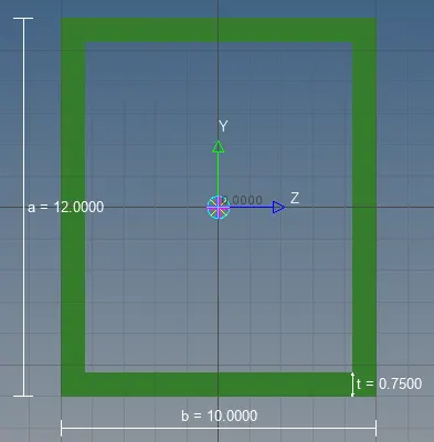
13. To create the box cross section select 1D-Hyperbeam-solid selection, select HYPERBEAM library, select standard thinwalled box and click create. Add dimensions a=12mm, b=10mm and t=0.75mm.
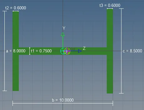
14. To create the I section select 1D-Hyperbeam-solid selection, select HYPERBEAM library, select standard I section and click create. Add dimensions a=8mm, b=10mm, c=8.5mm, t1 = 0.75mm, t2=0.6mm and t3=0.6mm.
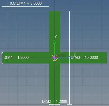
15. To create the X section select 1D-Hyperbeam-solid selection, select OPTISTRUCT library, select cross and click create. Add dimensions DIM1=5mm, DIM2=1.2mm, DIM3=10mm and DIM4=1.2mm.
16. Assign all the cross-sections to their respective properties and assign the appropriate properties to components 1,11 and 111.
17. To create mass element, select 1D-masses-select the nodes on the RBE2 links, give mass size as 10 and click create.
18. To create spring element, select 1D-springs-select nodes one each on the upper and lower bracket. Keep appropriate orientation.
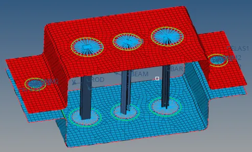
Result: The lD elements are created as per requirement.