Week 4-1D Element Creation Challenge
Mesh the Given component with the Size of 5 Units. Create 1D elements on the following component with given cross-section and DOF
- Rod element:- Translational DOF should be Constrained with RBE2 link
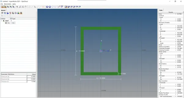
Cross-Section: BOX- Dimension a= 12 mm
dimension b=10 mm
Thickness t= 0.75 mm
- Beam element:- All DOF should be constrained with RBE3 link
Cross-Section: I Section- Dimension a= 8 mm
Dimension b= 10 mm
Dimension c= 8.5 mm
Thickness t1= 0.75 mm
Thickness t2= .6 mm
Thickness t3= .6 mm
- Bar element:- Constrain only x and y DOFs With RBE3 link
Cross-section: X section- Dimension DIM1= 5 mm
Thickness DIM2= 1.2 mm
Dimension DIM3= 10 mm
Thickness DIM4= 1.2mm
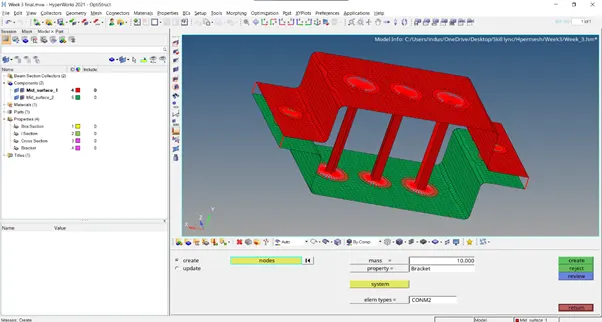
- & e. Apply the mass of magnitude 10 with the RBE2 link
- Join the two components with Spring elements
Procedure:-
Importing the Model
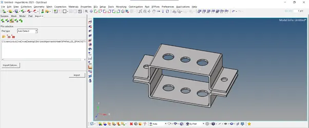
First of all import the given file into hypermesh
Go to Import solver deck, then click on import Geometry and select the file and Import
Creating Mid-Surface
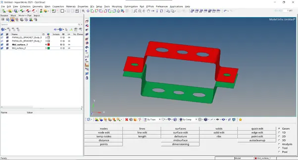
After Importing the file, now create the mid surface of the given component
To create the mid surface, go to Geometry and then click on Midsurface. After that select the component and then create the midsurface
Meshing
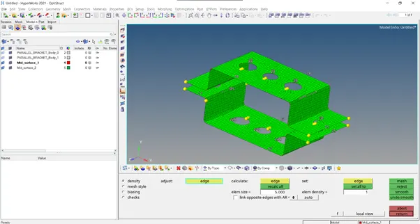
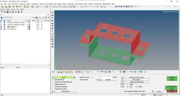
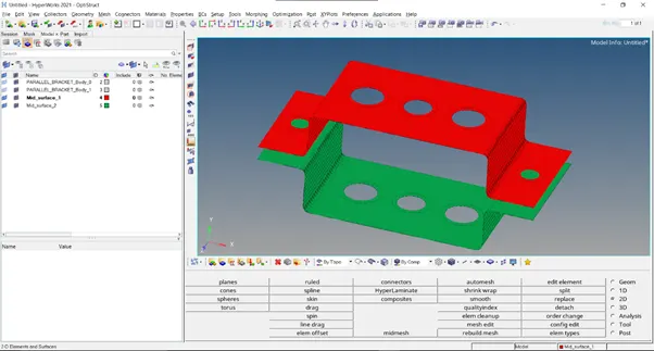
After Extracting the mid surface now mesh the given component. Go to 2D and then select automesh. Mesh the component by specifying element size as 5 units and select mixed type
Meshed Component
Creating Materials
Now to create the Hyperbeam structure, first define the Material

Click on the icon seen in the above image. This icon is for creating materials. Now define the material as ‘Steel’, select type as ‘Isotropic’ and give the Card image as ‘MAT1’

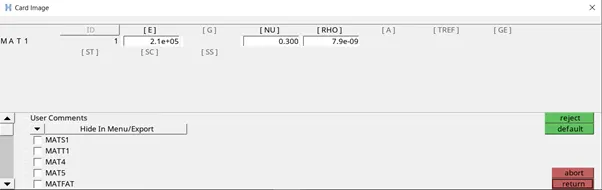
Now click on ‘create/edit’. A window will open and inside that enable the material properties such as [E] , [NU] , [RHO]
Hyperbeam
Now create ROD, BEAM and BAR element by clicking on Hyperbeam under 1D
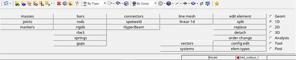
Now select ‘Standard Section’. Under Standard section library we can select anyone of the following ‘Hyperbeam’ or ‘Optistruct’.

Box Section
Under standard section type select ‘BOX1’ and click create. After doing this another window will open as seen in the image below
Specify the Dimensions and then click on the below icon to return to the previous window 
I-Section
Do the same thing by selecting ‘I-section’ and ‘Cross section’ in the standard section type. Specify the dimensions and return to the previous window
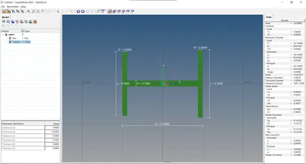
Cross Section
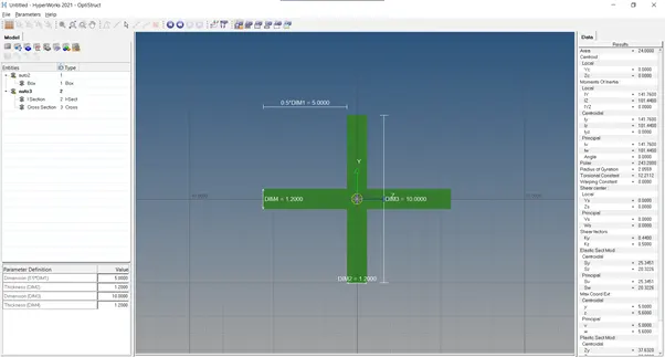
Creating Properties
Now create Properties by clicking on the below icon 
Create the following properties as given below. One for the 2D element and rest three for the Hyperbeam element
To create the property for the extracted mid surface, type the desired name in the ‘prop name’ box, then select the type which will be 2D in this case, specify the card image as ‘PSHELL’ and select the material ‘Steel’ and create it

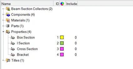
Do this for the three Hyperbeam element that is seen in the image. The only thing is that under Type select 1D and under card image select ‘PROD’, ‘PBAR’ and ‘PBEAM’ according to the specifications mentioned above
Creating RBE2 and RBE3 links.
In 1D got to rigids and select the element type as RBE2. Select the nodes and constrain the desired DOF and create it
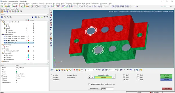
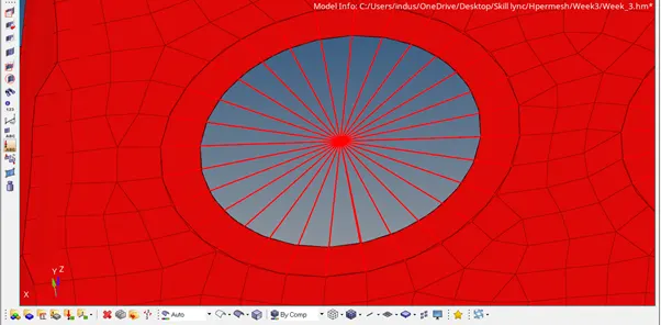
Now to create RBE3, click on rbe3 in 1D. Select the nodes and constrain the desired DOF and then create

Creating Rod element
Go to 1D. Under that select ‘Rod’ and then specify the nodes. Select the property as ‘Box Section’ (in our case) and select element type as ‘CROD’ and return
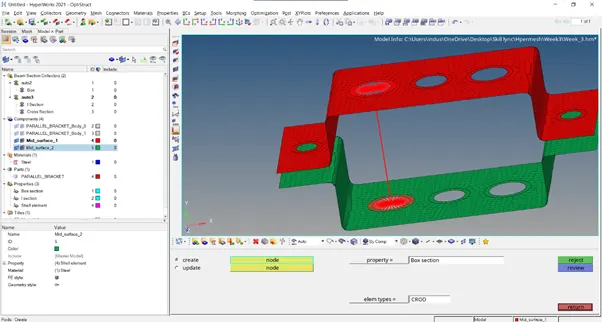
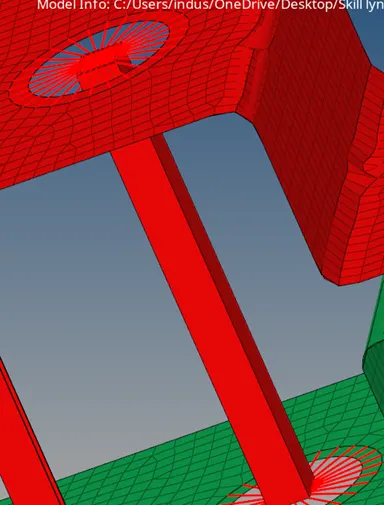
Creating Beam Element
Under 1D click on ‘bars’. Now select the nodes and specify property type as ‘I-Section’. After this select element type as ‘CBEAM’ and then return
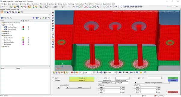
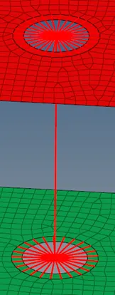
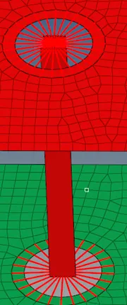
Creating Bar Element
Under 1D click on ‘bars’. Now select the nodes and specify property type as ‘Cross-Section’. After this select element type as ‘CBAR’ and then return
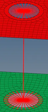
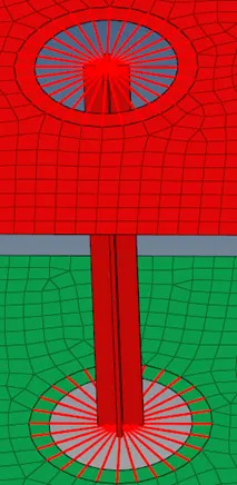
All Elements created
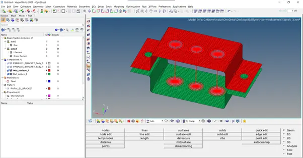
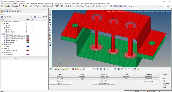
Creating Mass
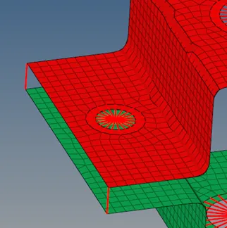
Now applying mass of 10 at points ‘d’ and ‘e’
Select ‘masses’ under 1D. Now select the nodes at points ‘d’ and ‘e’ and specify the magnitude of mass as 10 and then return

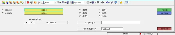
Creating Spring element
Select Springs under 1D. Now select the nodes at point ‘f’ and select element types as ‘CELAS1’ and then return
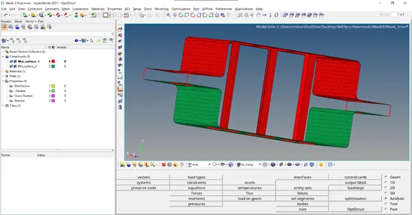
Final Model
Conclusion:- Created Mid-surface of the given component
Created Hyperbeam element i.e BOX , I , CROSS section
Creating RBE2 and RBE3 link
Creating masses and joining the element by springs