Week - 4
IMPLEMENTATION OF THE CONTROL LOGIC OF WASHING MACHINE AND GEAR SHIFT USING STATE FLOW
Aim: To implement the control logic using the state flow chart in simulink library and show the results according to the given situations:
- Implement control logic of a “washing machine”
- If the power supply is available, the system gets activated
- If the Water supply is not available, stop the process & indicate through LED
- Soaking time should be 200s followed by Washing time of 100s.
- Then rinsing happens for next 20s & dryer runs for 50s
After all the processes have completed turn on the finished LED
2. Make a Simulink chart for the “Gear shift” logic as per below conditions:
|
Speed Range(kmph) |
Gear |
|
0 to 15 |
1 |
|
16 to 25 |
2 |
|
26 to 40 |
3 |
|
41 to 60 |
4 |
|
Above 61 |
5 |
THEORY
Stateflow is a control logic tool used to model reactive systems via state machines and flow charts within a Simulink model. Stateflow uses a variant of the finite-state machine notation established by David Harel, enabling the representation of hierarchy, parallelism and history within a state chart. Stateflow also provides state transition tables and truth tables.
1) Implementing the control logic of the washing machine
The state flow chart of the washing machine that has to work according to the given condition is shown below in fig 1.1. The embedded system of washing machine 1st checks for the power supply and then water supply, and then does soaking, washing, rinsing, drying respectively and then finally activates the finish lamp as green when the task gets finished.
The symbols plane in fig 1.2 shows the input data and out put data that are initialized by the usser.
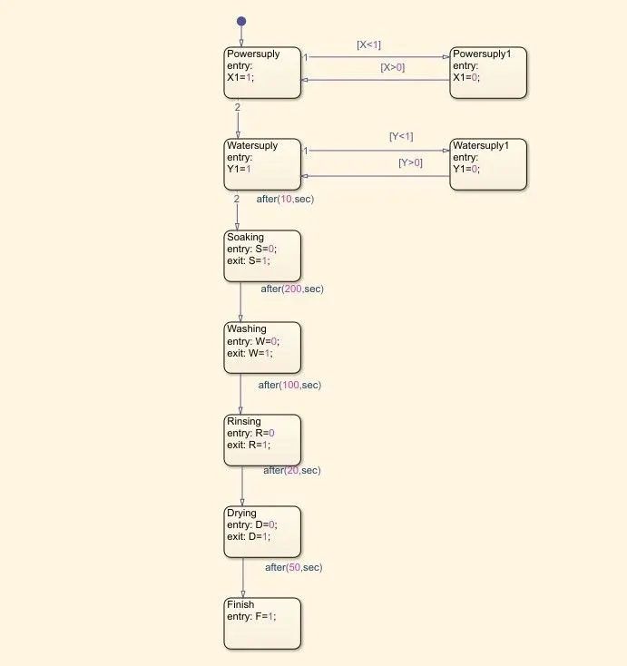
Fig 1.1: State flow of the washing machine
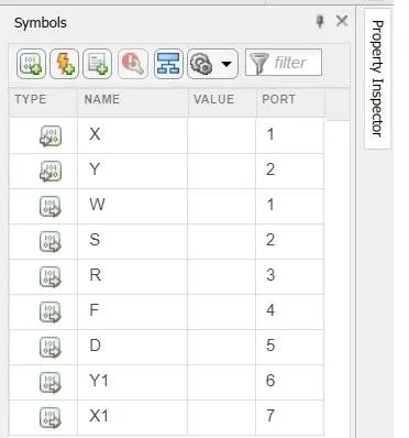
Fig 1.2: Symbols plane
RESULT
The fig 1.3 and 1.4 shows the input sources and the output indicators when there is water supply and when there is no water supply respectively. We can observe that the colour of the indicator light is different in both cases because of the control logic given in the state flow.
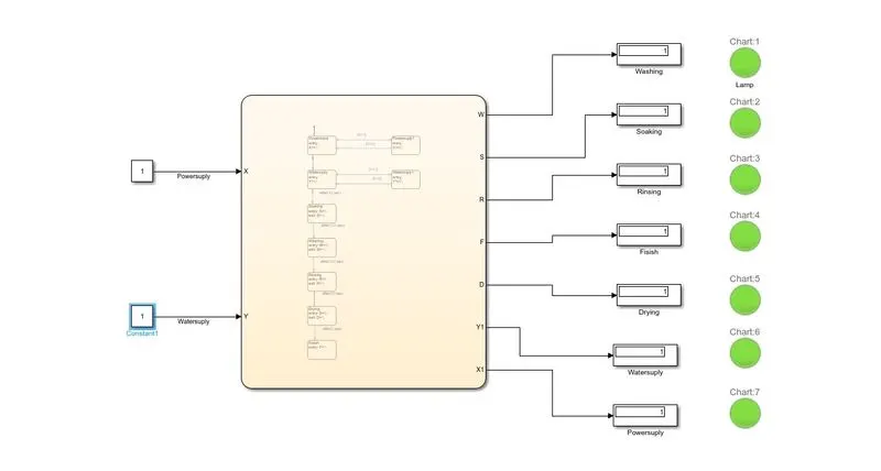
Fig 1.3: When both power suply and water suply is active
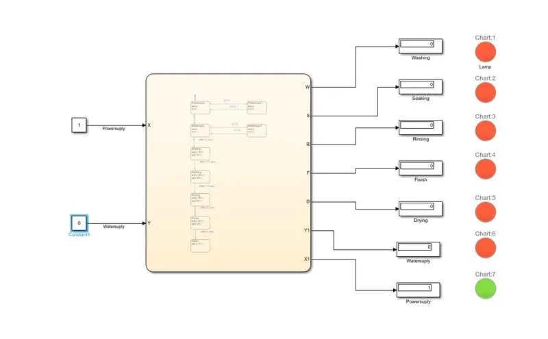
Fig 1.4: When powe suply is active and watersuply is inactive
2) Gear Shift Logic
The state flow of the gear shift mechanism is shown in fig 2.1, the speed ranging from 0-15kmph is for 1st gear after 15kmph it automatically shifts to the second and so on.
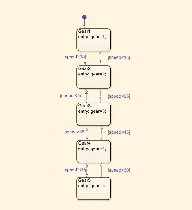
Fig 2.1: Gear shift lofic state flow
The speed is controled by the slider gain which is provided as the iput to the gear shift logic .
RESULT
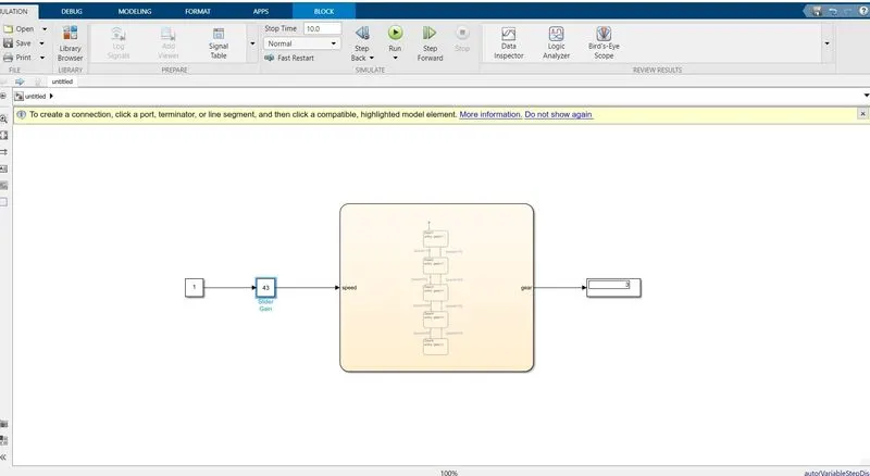
Fig 2.2: The simulink model of the gear shift logic using a state flow chart
From the above result we could observe that the slider gain value is showing a value below 45 kmph and hence the display shows the value 3 which indicates 3rd gear, Similarly for a speed value for 100 the gear would be in 5th position. Hence the model is the final output of the given conditions mentioned above.
CONCLUSION
The state flow analysis of the control logic of washing machine and the gear shift logic are sucessfully simulated using simulink workspace and the results are shown above.