Week -2
SIMULINK MODEL OF A DOORBELL AND THERMISTOR
Aim:
1) To make simulink model of a doorbell using solenoid block
2) to use thermistor to control the switching of the fan
Objective:
- To observe the physical movement of the plunger, when the switch is off for 2 sec
- To turn on and off the fan using the temperature conditions sensed by the thermistor
- Temperature source: 20 °C from 0 to 10 seconds, 27 °C from 10 to 30 seconds, 23 °C from 30 to 50 seconds
- Fan conditions: ON if the temperature above 25 °C, OFF otherwise
1. SIMULINK MODEL OF A DOOR BELL
THEORY:
Solenoid:
A solenoid is a device consisting of a coil of wire, the housing and a moveable plunger (armature). When an electrical current is introduced, a magnetic field forms around the coil which draws the plunger in. More simply, a solenoid converts electrical energy into mechanical work.
The coil is made of many turns of tightly wound copper wire. When an electrical current flows through this wire, a strong magnetic field/flux is created.The housing, usually made of iron or steel, surrounds the coil concentrating the magnetic field generated by the coil.The plunger is attracted to the stop through the concentration of the magnetic field providing the mechanical force to do work.
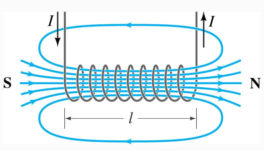
Fig 1.1: Solenoid
Working:
The heart of a doorbell is an electromagnet. Electromagnets are coils of wire wrapped around a small piece of magenetic metal. When electricty passes through the wire, it creates a maganetic field around the wire.
When you press a doorbell button, you complete an electrical circuit that allows household electricty to flow through the doorbell's internal electromagnet. The magnetic field generated by the electromagnet is then used to power a mechanism that creates the doorbell sound.
SIMULINK MODEL:
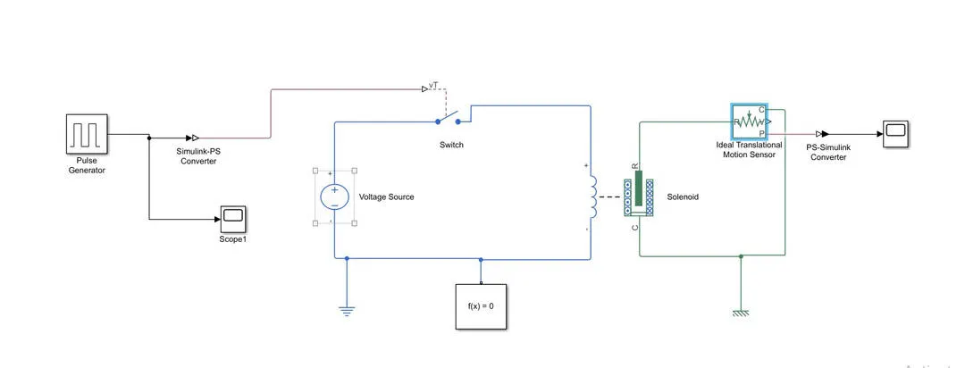
Fig 1.2: Simulink block diagram of simple door bell
Pulse generator input values:
Amplitude: 1
Period (secs): 4
Pulse Width (% of period): 50
Phase delay (secs): 2
Solenoid parameters (case 1):
Spring constant: 200
Stroke for zero spring force: 5
Damping: 1
Plunger mass: 0.05
Solenoid parameters (case 2):
Spring constant: 50
Stroke for zero spring force: 2
Damping: 3
Plunger mass: 0.05
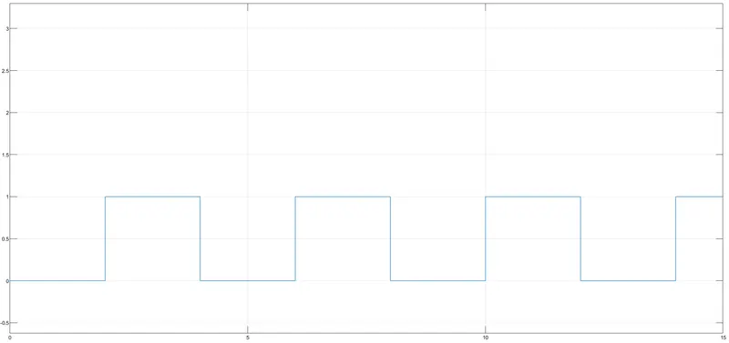
Fig 1.5: Input from pulse generator
RESULT:
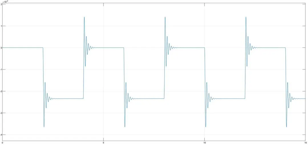
Fig 1.4: Result for case 1 parameters
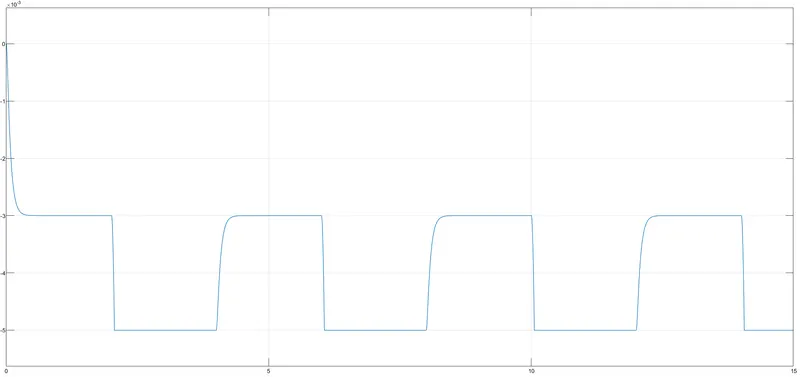
Fig 1.5: Result for case 2 parameters
CONCLUSION:
From the above two results we could infer that when switch is closed the electromagnet receives electrical power from the battery and hence pulls the metal arm to hit the bell which produces the sound. In the first case the result is shown in fig 1.4 which shows a distortion at each interval, this is due to the poor damping of the solenoid and also depends on the spring constant of the spring used. But in fig 1.5 the result is much smooth in every cycle because the spring and damping constant of the solenoid are different and hence a better damping.
- SIMULINK MODEL OF A SWITCH CONTROLLED BY THERMISTOR
THEORY:
Thermistor:
A thermistor is a type of resistor whose resistanceis strongly dependent on temperature, more so than in standard resistors. The word is a combination of thermal and resistor. Thermistors are widely used as inrush current limiters, temperature sensors (negative temperature coefficient or NTC type typically), self resisting overcurrent protectors, and self-regulating heating elements (positive temperature coefficient or PTC type typically).
SIMULINK MODEL:
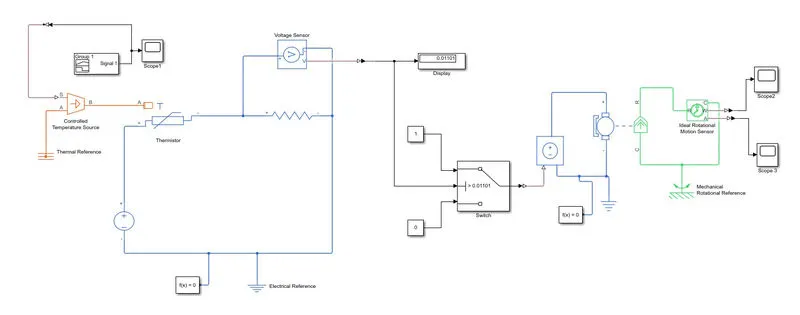
Fig 2.1: Simulink model of thermistor controlled switch
The figure above shows the basic simulink model of fan controlled by a switch which turns on and off as per the temperature sensed by the thermistor. As we can see there is a controlled temperature source which is fed by the signal builder block. The signal builder block is defined with a discrete signal which is shown in fig 2.2, according to the given conditions.
The temperature source is then connected to the thermistor which senses the temperature and varies the resistance accordingly hence by varying the voltage source across it protionally. This voltage variation is sensed by the voltage sensor that is connected across the resistor.
This voltage signal is then given to the switch whose threshold value is set from the display value that we obtain from the voltage sensor to control the switching according to the conditions.
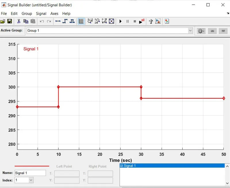
Fig 2.2: Input to the controlled temperature source
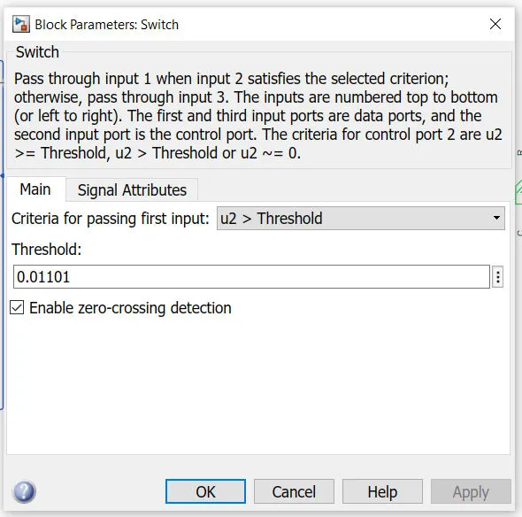
Fig 2.3: Switch Threshold
RESULT :
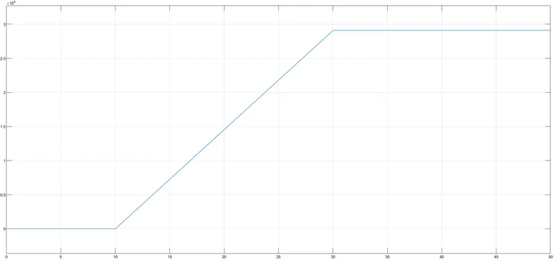
Fig 2.4: Angular displacement
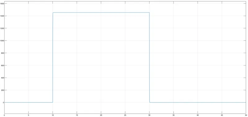
Fig 2.5: Angular velocity
We can see that there are two graphs which are obtained from two scopes connected to the angular velocity sensor. One is connected to purt W and other is connected to port A.
The block represents an ideal mechanical rotational motion sensor, that is, a device that converts an across variable measured between two mechanical rotational nodes into a control signal proportional to angular velocity or angle. The sensor is ideal since it does not account for inertia, friction, delays, energy consumption, and so on.
Connections R and C are mechanical rotational conserving ports and connections W and A are physical signal output ports for velocity and angular displacement, respectively.
CONCLUSION:
For 0 to 10 seconds fan is OFF condition because temperature is 293K which is below the threshold 298K Alter 10 temperature goes to 300K then the switch will be in ON condition as the temperature exceeds 299K After 30s fan will turn OFF as the temperature comes down to 296K which is below the threshold temperature of 298K