Washing Machine Mechanism and Gear Shifting Logic using Simulink
Aim:
The main aim is to determine the working of the Washing Machine Mechanism and Gear Shift Logic using the Simulink State flow.
Objective:
- The first objective is to create a Control Logic of a Washing Machine using Stateflow as per the given Sequence:
- If the Power Supply is available, the system gets activated.
- If the Water supply is not available, stop the process & indicate through LED
- Soaking time should be 200s followed by Washing time of 100s.
- Then rinsing happens for the next 20s & dryer runs for 50s
- After all the processes have completed turn on the finished LED
- The second objective is to make a Simulink Chart for the Gear Shift Logic as per the given sequence
|
Speed Range(KmpH) |
Gear |
|
0 to 15 |
1 |
|
16 to 25 |
2 |
|
26 to 40 |
3 |
|
41 to 60 |
4 |
|
Above 61 |
5 |
Give speed input while the simulation is running & display the gear number.
Theory:
Washing Machine:
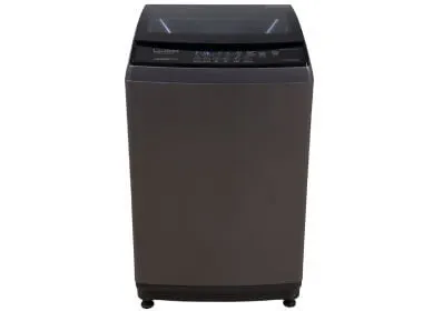
A Washing Machine is a home appliance used to wash laundry. The term is mostly applied to machines that use water as opposed to dry cleaning or ultrasonic cleaners.
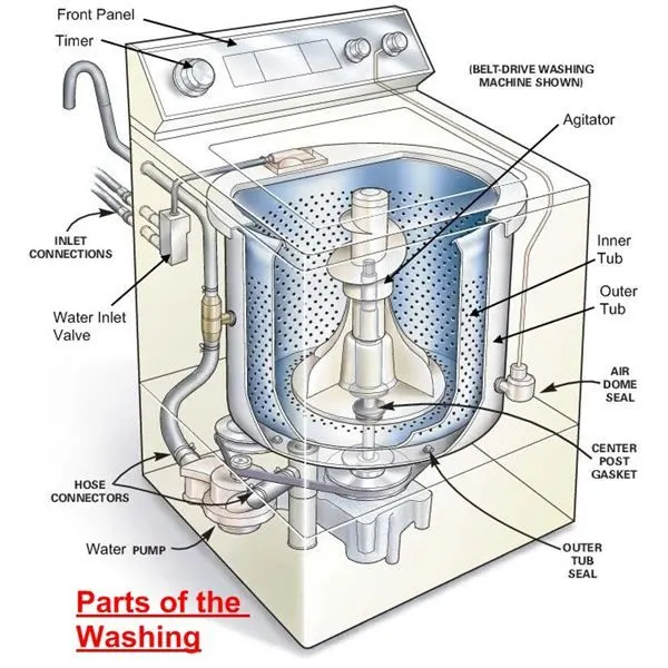
During the wash cycle, the outer tub is filled with water sufficient to fully immerse and suspend the clothing freely in the basket. The movement of the agitator pushes water outward between the paddles towards the edge of the tub. The water then moves outward, up the sides of the basket, towards the center, and then down towards the agitator to repeat the process, in a circulation pattern similar to the shape of a torus. The agitator direction is periodically reversed because continuous motion in one direction would just lead to the water spinning around the basket with the agitator rather than the water being pumped in the torus-shaped motion. Some washers supplement the water-pumping action of the agitator with a large rotating screw on the shaft above the agitator, to help move water downwards in the center of the basket.
Gear Transmission:
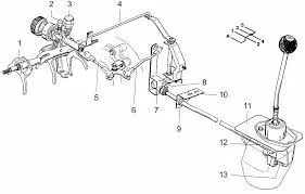
The gear shifter is responsible for physically engaging the gears on the output shaft, locking them in place so that they turn the shaft and send torque to the drive wheels. This is where visuals are really useful. Moving the shifter into position engages the gear selector forks.
The gear shifter and clutch pedal are the two inputs by which a driver operates a manual transmission, though if we’re being technical the shifter is the only piece of this whole puzzle that is operated manually.
The transmission housing contains three shafts interacting with one another. One of them is attached to the engine (the input shaft), one is attached to the differential (the output shaft), and the third shaft, often called the layshaft or the countershaft, interacts with the other two via a system of gears. While your car is on, the engine shaft is always turning, even while stopped. It has to keep going otherwise the engine doesn’t work.
Procedure:
- For Washing Machine:
- To implement the control logic, open the Simulink blank workspace.
- Double-click on the empty workspace and type chart. A new block is created.
- Now, double-click on the chart block to open a new workbench.
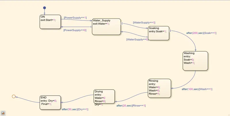
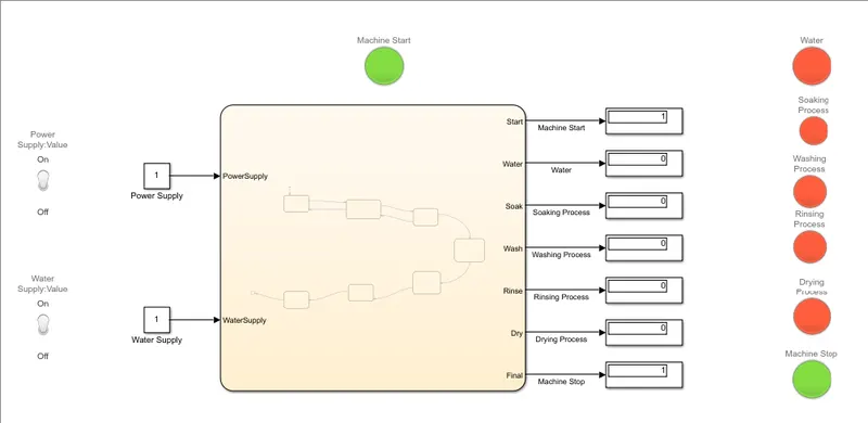
- Click on the state block to create a block and give the name “ON” and type exit: Start=1 which creates a function when the block runs the machine will start.
- Next, Create another block that contains the water supply and it exits when the water ==1 such that when the water supply is not given it switches off the power supply.
- These Blocks are connected by the connecting lines which consist of a power supply logic which when is switched on it follows the process created.
- Now, we have to create a Soaking block such that the water supply is given and logic is considered such that after 200 seconds the Soaking should be done.
- After soaking is done, the Washing block is created with the logic that the wash should be completed after 100 seconds.
- The next process after washing is rinsing. Rinsing is done for 20 seconds and then it is sent to Drying Block.
- In the Drying Block, the clothes are dried for 50 seconds, and then the Machine Stops.
- After Creating the Required blocks, go to the Simulink workspace and save the file and make sure all the output and input connection ports are given properly.
- To check the ports, Go to the Chart Workbench, and in the prepare section, in the Configuration and Simulation, select the Symbols Pane. And check the ports and their sequence.
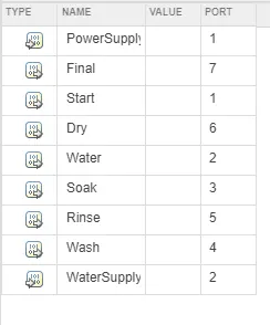
- Now, in the Simulink workbench, give the output connections to display and the input connections as the constants.
- Now Lamps and Switches are connected to the outputs and inputs respectively.
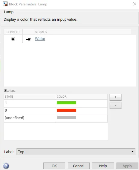
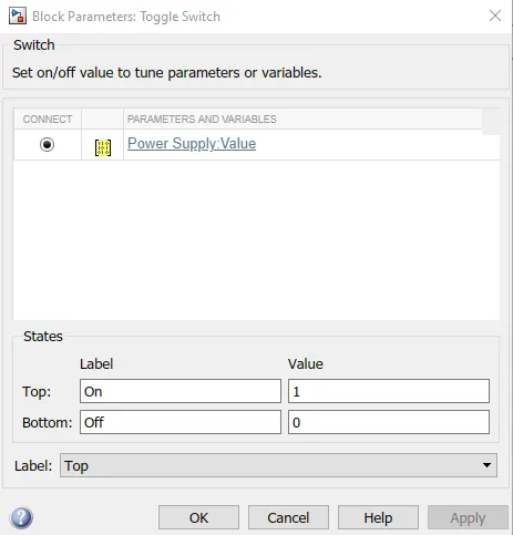
- Run the simulation and observe the analysis.
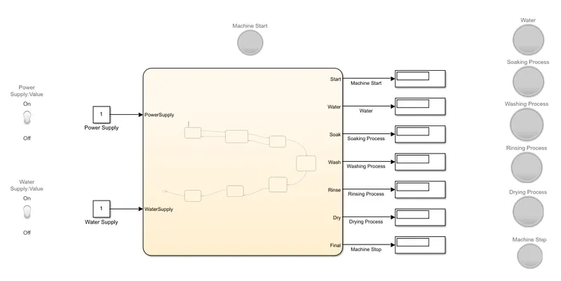
- For Gear Shift Logic:
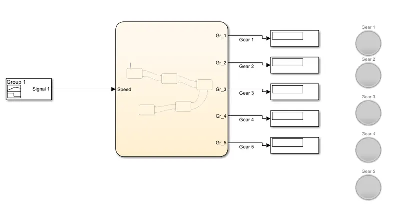
- The Gear shifting logic is created in the Chart state flow.
- Use the State block to create the different gears from 1 to 5 with entry as 1 and exit as 0.
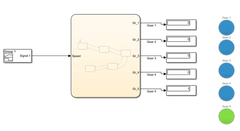
- Now, Connect the Gear 1 and 2 with a logic that if the Speed is greater than 16 then it shifts to Gear 2 and if the speed is less than 15 it changes to gear 1 from gear 2.
- Gear 2 and 3 also follow the same logic that if the speed is more than 26 it changes to gear 3 and if the speed is less than 25 it decreases to gear 2 from gear 3.
- Gear 3 and 4 also follow the same logic that if the speed is more than 41 it changes to gear 4 and if the speed is less than 40 it decreases to gear 3 from gear 4.
- Gear 4 and 5 also follow the same logic that if the speed is more than 61 it changes to gear 5 and if the speed is less than 60 it decreases to gear 4 from gear 5.
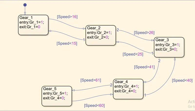
- Now, the connections are established, and make sure that the output ports are given such that all the gears are considered as outputs and speed is taken as input.
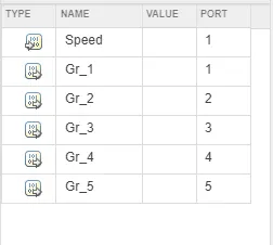
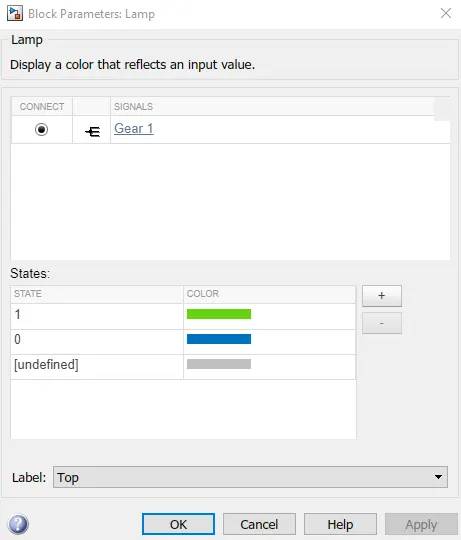
- For all the outputs the display blocks are created. The lamp is connected to the gears.
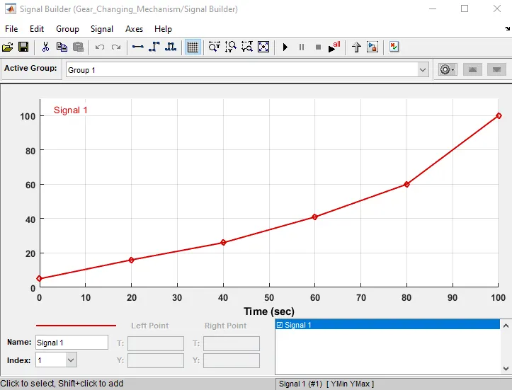
- The input signal builder is created with a graph created such that the speed increases.
- Run the Simulation and observe the results.
Result:
Washing Machine:
Gear Shifting:
Blocks Used:
- Chart:
A finite State machine is a representation of an event-driven (reactive) system. In an event-driven system, the system responds to an event by making a transition from one state to another. This Transition occurs if the condition defining the change is true.

- Display:
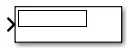
The Display block shows the value of the input data. You can specify the frequency of the display. For numeric input data, you can also specify the format of the display.
- Constant:
The constant block generates a real or complex constant value signal.

- Lamp:
The Lamp block displays a color indicating the value of the input signal. You can use the lamp block with other dashboard blocks to build an interactive dashboard of controls and indicators for your model. You can specify pairs of input values and colors to provide the information needed during the simulation.

- Toggle Switch:
The Toggle Switch block toggles the value of the connected block parameter between two values during simulation. Use the Toggle Switch block with other Dashboard blocks to create an interactive dashboard for your model.
For example, you can connect the Toggle Switch block to a Switch block in your model and change its state during simulation.

Learning Outcomes:
- Learned to create the states with control logic.
- Learned to use the dashboard efficiently.