Control logic of washing machine and gear shift using Simulink Stateflow chart.
Objective:
- To implement control logic for "washing machine" using Stateflow.
- Make a Simulink chart for the "gear shift" logic as per the given conditions.
1-Control logic for "Washing machine"
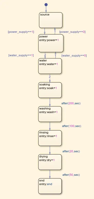
Stateflow chart for washing machine given below:
Explanation:
- Here we used the stateflow chart block in it we used different state blocks to define the given conditions for washing machine operation.
- Starting block used is for source and followed block is for power supply with the conditions if supply is1 then the flow will continue else it will go back to source block.
- Then followed to next block which is for water supply and there also conditions are been applied if there is watersupply it will continue to state flow else it will go back to power supply block.
- After that blocks used are for soakink,washing,rinsing and drying with specified conditions of soaking should be done for 200s,after that washing should be done for 100s followed by rinsing for 20s and drying for 50s and then end the process.
Results:
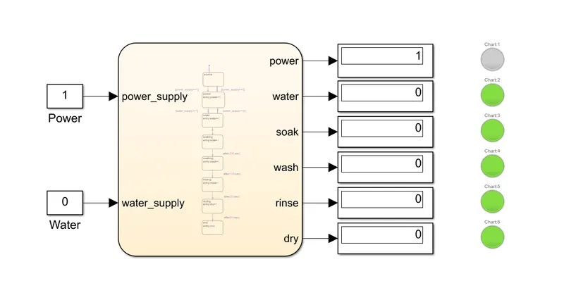
- condition-1=When the power supply is 1 and water supply is 0 and the model is run for 10 s.
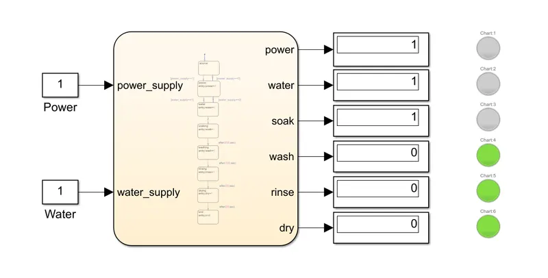
- condition-2=When the power supply and water supply both are 1 and the model run time is 10s.
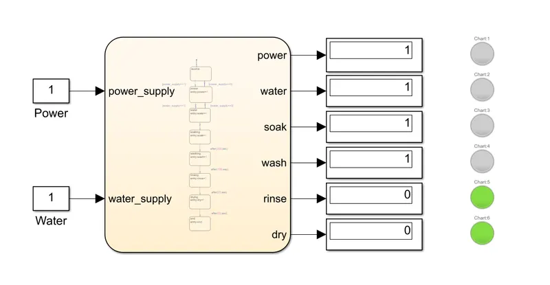
- condition-3=When both powersupply and water supply is 1 but the run time is 200s
- condition-4=When power supply and water supply are 1 and the run time is 300s.
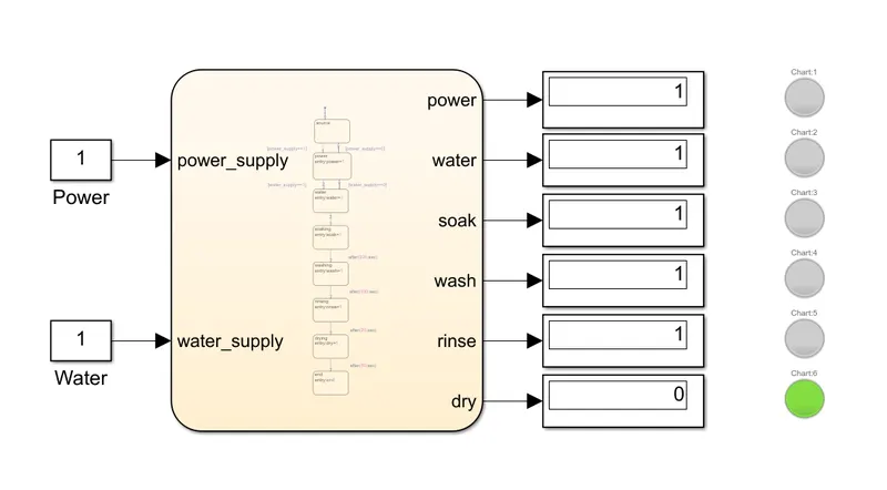
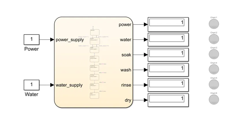
- condition-5=When the power and water supply are 1 and run time is 350 s.
2-Simulink chart for "gear shift"model:
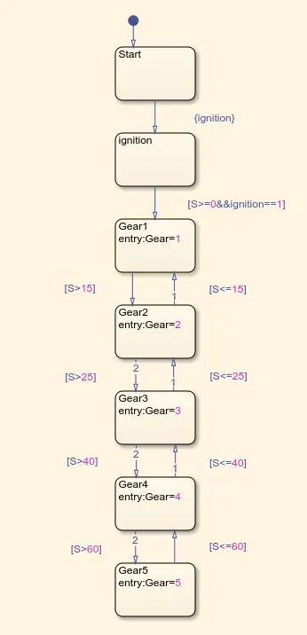
Stateflow model for "gear shift" at different conditions.
Explanation:
- First we got the state block and named as start and followed to that we gave ignition block and gave condition after start of the vehicle if engine gets ignite then it will shift to the gear or else it will go to start.
- After that we gave speed condition if its greater than 0 and ignite is 1 then it will shift to first gear.
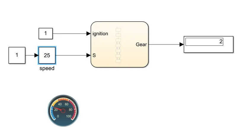
- After that if the speed is between 0-15 the there is no shifting of gear and if the speed increases to 16-25 then gear is shifted 2 gear.
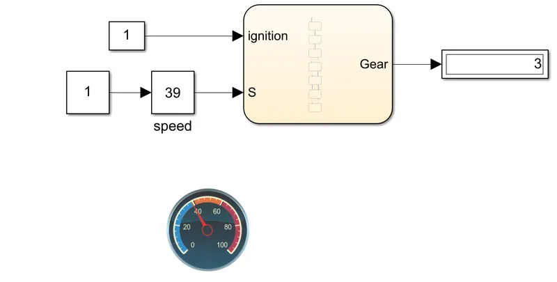
- After this if the speed increases to 26-40 gear gets shifted to 3 gear else it will be on secong gear if speed is less than 26.
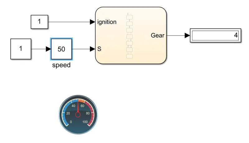
- After the speed increases from 41-60 gear is shifted to 4 gear or else it will be on 3 gear if speed is less than 41.
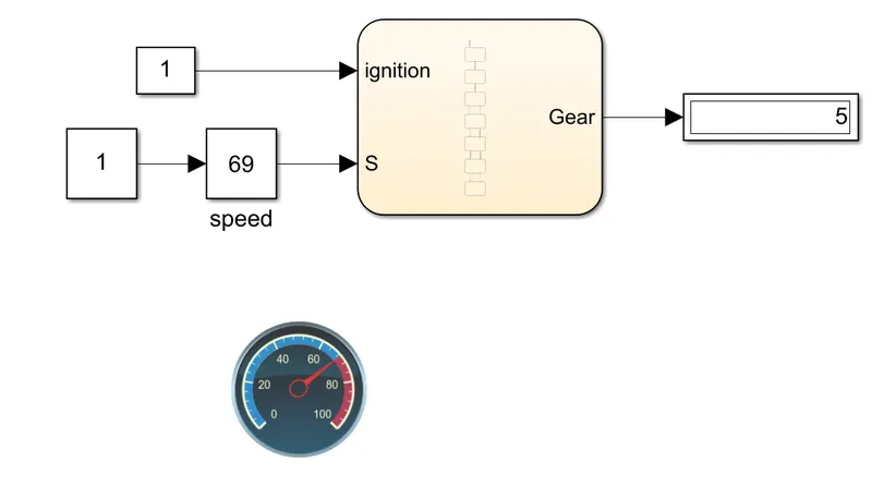
- Finally if the speed is above 61 the gear is shifted to 5 gear.
Results:
- condition-1=when the speed is less than 15kmph the gear is 1.
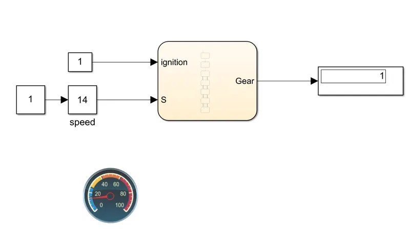
- condition-2=When the speed is greater than 15kmph and less than 26kmph the gear is 2.
- condition-3=When the speed is greater than 26kmph and less than 40 kmph gear is 3.
- condition-4-When the speed is greater than 40kmph and less than 60 kmph the gear is 4
- condition-5=When the speed is above 61kmph the gear is 5.
Conclusion: Implemented the control logic for "washing machine"and "gear shift" using stateflow and ploted the reults as per the given conditions.