Week - 4
SIMULINK MODEL FOR WASHING MACHINE USING STATE FLOW
AIM
Implement control logic of a washing machine using stateflow according to the given condition for power input & water input. As per this machine operates.
OBJECTIVE
Given sequence to implement control logic of a washing machine using state flow is:
- If the power supply is available, the system gets activated.
- If the water supply is not available, stop the process & indicate through LED.
- Soaking time should be 200 sec followed by washing time of 100 sec.
- Then rinsing happens for next 20 sec & dryer runs for 50 sec after all the processes have completed turn ON the finished LED.
EXPLANATION
State flow: State flow can be best explained as a graphical representation of a machine consisting of states, transitions & conditions. A state flow chart can be created to define how MATLAB & simulink model reacts to external input signals, events & time based conditions.
Working of Washing Machine
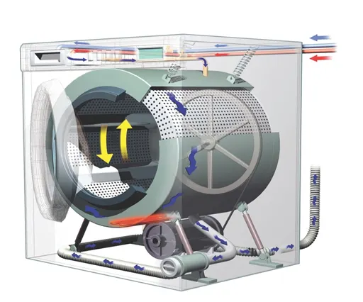
Fig1: Working Model for Washing Machine
The working principle of a washing machine is centrifugation. Centrifugation is a separation process which uses the action of centrifugal force to promote accelerated settling of a particles in a solid-liquid mixture. The washing machine concept is pretty simple. It agitates cloths in a soapy suds & water to remove any dirt & stains before spinning to the drain the water after the cycle. The main components of washing machine is drum which fills up with water. It actually has two drums. Washing machine is made up of:
Inner Drum: This is where we put the cloths when we are ready to wash. We will notice this drum rotates a bit when we touch it & there are a lot of holes punched into the drum. These allow the water to come in & wash the cloths.
Paddles: These are the ridges that lie on the edge of the drum & help move your cloths around while being washed.
Agitator: These are more common in top load machine & paddle in the middle that helps turn the cloths around in the soapy water.
The outer drum: There is another drum that holds the water while inner drum or agitator rotates. This part is completely water tight to prevent machine from leaking all over.
Thermostat & heating element: These control the temperature of water & heats up the water to specified temperature.
Pump: This removes water from drum after wash.
Programmer: This controls the washing machine through all the steps from soaking to rinsing, washing & drying.
Pipes & valves: These allow water in & out of washer.
Rinsing, soaking, washing, drying these all performances washing machine does when we give power supply & start the programme. Programme such as delicate wash, colour wash or pre-soak are one of the features of washing machine.
Procedure:
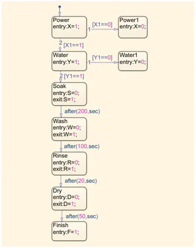
Fig2: State flow formed for Washing Machine
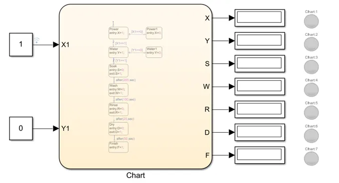
Fig3: Simulink Model for Washing Machine
- With the help of stateflow we have simulated complete operation of a washing machine right from power off to drying & termination of cycle.
- The model we have formed in such a way that if power supply is available, the system gets activated & if water supply is not avialble, the process is terminated & this indicated through lamp.
- We have created a chart block for defining the stateflow as per given conditions.
- If power is off i.e. 0, the process is terminated at the junction. If the power is ON i.e. 1 the process is activated.
- If water is off i.e. 0, the process is terminated. If water is ON i.e. 1, the process is activated.
- After this soaking block gets activated & action takes place.
- After 200 sec of soaking, wash block gets activated & washing action takes place.
- After 100 sec of washing, rinse block gets activated & rinsing action takes place.
- After 20 sec of rinsing, dry block gets activated & drying action takes place.
- After 50 sec of dry, finish block gets activated. Finish is to terminate the signal flow in the process & exits the chart.
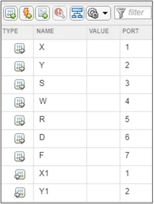
- Here power & water is defined as inputs where as soak, wash, rinse, dry, finish as outputs.
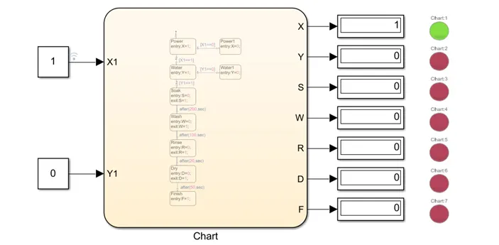
- We have moved out of chart & then connected constant block as 0 & 1 to input ports X1 & Y1.
- And we have connected displays & lamps to output ports X, Y, S, W, R, D, F to check the results.
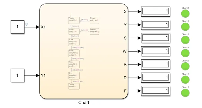
- Then after running the simulation for infinite times, for input power=1, water=0 only power lamp gets activated & rest turned off.For input power=1, water=1 all lamp gets activated as per the given condition.
RESULT
When Power is ON & Water is OFF
When Power is ON & Water is ON
CONCLUSION
We have successfully formed simulink model for automatic washing machine by implementing control logic of washing machine using stateflow according to the sequence provided in the question & after finishing all the processes, the LED light turns green indicating that the process is finished.
SIMULINK MODEL FOR GEAR SHIFT USING STATEFLOW
AIM
Create the stateflow for gear shift & vary the speed as input & obtain the output as the gear number in display.
OBJECTIVE
To make simulink chart for the gear shift logic as per below conditions:
|
Speed Range (kmph) |
Gear |
|
0 to 15 |
1 |
|
16 to 25 |
2 |
|
26 to 40 |
3 |
|
41 to 60 |
4 |
|
above 61 |
5 |
Give speed input while the simulation is running & display the gear number.
EXPLANATION
Gear Shift
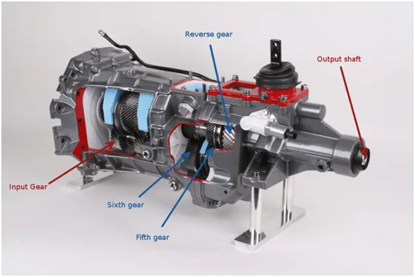
Fig1: Working Model for Gear Shift
Gears are used for transmitting power from one part of machine to another. The gear shifter allows the vehicle to be put into different gears on a manual transmission. In an automatic transmission, the gear shifter is known as a gear selector. The gear shifter is normally located between the two front seats of vehicle on a manual transmission. The gear knob is the top of the gear shifter & includes the shift pattern that guides the gear selection. The shift pattern indicates which way the gear shifter should be moved when selecting a certain gear. A manual gearbox is the type of transmission that allows the driver to select the gear by gear shifter. We must push the clutch pedal which disengages the gear box from engine, move the gear shifter into the correct gear & clutch can be released. An automatic gear box does not need the driver to manually shift gears, instead the gear selection is done by the on board computer. The automatic gear box are connected to the engine by a torque converter, so they do not have a clutch.
Procedure:
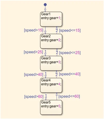
Fig2: State Flow for Gear Shift
- We have created a chart block for defining the stateflow for gear shaft as per the given conditions.
- If speed is greater than 0 or less than or equal to 15 the flow is terminated and gear 1 is activated.
- If speed is greater than 15 & less than or equal to 25, the flow s terminated and gear 2 is activated.
- If speed is greater than 25 & less than or equal to 40, the flow is terminated and gear 3 is activated.
- If speed is greater than 40 & less than or equal to 60, the flow is terminated and gear 4 is activated.
- If speed is greater than 60 & the flow is terminated and gear 5 is activated.
- Speed is defined as input & gear is defined as output.
- We have moved out of chart & then connected constant block varing input with slider gain block as a speed & we also displayed output using display block which is basically the gear number.
- Then after running the programme for infinite times we got the simulation results.
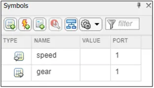
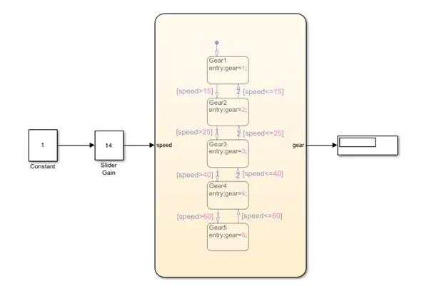
Fig3: Simulink Model for Gear Shift
RESULT
SPEED<15
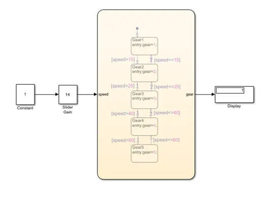
SPEED>15
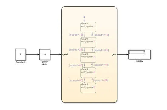
SPEED>25
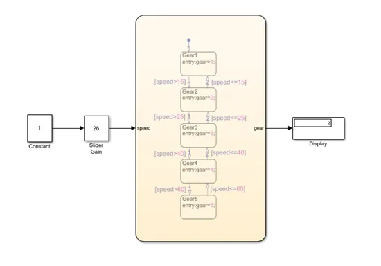
SPEED>40
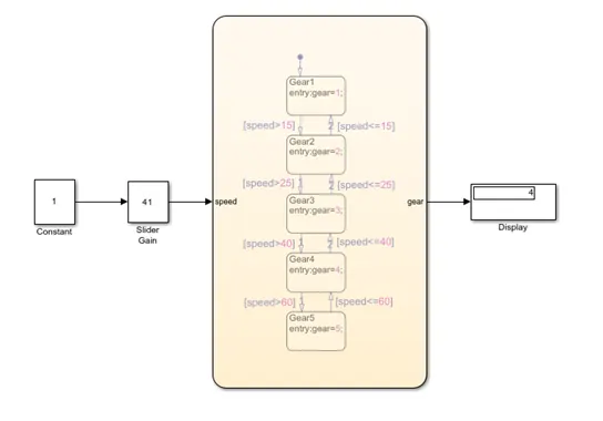
SPEED>60
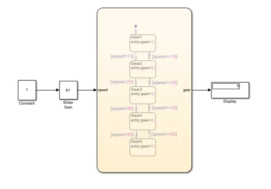
CONCLUSION
Thus we have formed a simulink model for a gear shifting mechanism which changes the gear the different ranges of speed.