Week -2
SIMULINK MODEL OF DOORBELL USING SOLENOID BLOCK
AIM
Create a Simulink model of Doorbell using Solenoid Block. Operate the Door bell simulink model system and plot the results.
OBJECTIVE
Create a situation where the switch is closed for 2 secs and then released. Observe the physical movemet of parameter.
EXPLANATION
What is Solenoid
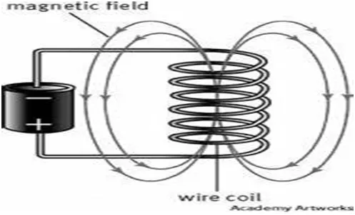
Fig 1: Solenoid Diagram
A solenoid is a device comprised of a coil of a wire, the housing and a movable plunger (armature). When an electric current is introduced, a magnetic field forms around the coil which draws the plunger in. More simply, a solenoid converts electrical energy into mechanical work.
- The coil is made up of many turns of tightly wound copper wire. When an electrical current flows through this wire, a strong magnetic field /flux is created.
- The housing, usually made of iron or steel, surrounds the coil concentrating the magnetic field generated by the coil.
- The plunger is attracted to the stop through the concentration of the magnetic field proving the mechanical force to do work.
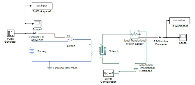
Fig2: Simulation Model of Door-bell using Solenoid Block
- In Door bell arrangement , when the switch is closed the electromagnet receives electrical power from the battery and pull the metal arm to hit the bell producing sound. Here Solenoid block work as door bell for this simulink model.
- Solenoid block is connected to switch and battery, and then electrical circuit is formed.
- The pulse generator is used to create square wave pulses at regular intervals which is used as a input source for the Solenoid block.
- But the Solenoid block is physical circuit and pulse generator of output signal is not physical so we need to connect simulink to PS converter.
- The switch block model which we used here, a switch is controlled by an external physical signal. If external physical signal PS is greater than the value specified in threshold parameter, then the switch is closed, otherwise the switch is open.
- Positive terminal of battery is connected to switch and negative terminal is connected to electrical reference.
- Ideal translational motion sensor is connected to Solenoid block R to observe the physical movement of the plunger.
- Connecting ports R and C are mechanical translational converting ports that connects the block to the nodes whose motion is being monitored.
- Connections V and P are physical signal output port for velocity and position respectively. In this block velocity is measured from port R to port C. Port C is connected to mechanical translational reference.
- Each physical network represented by a simscape block diagram requires solver setting information for simulation.
- The solver configuration block specifies the solver parameters that model needs before starting of simulation.The output of ideal motion sensor is given to scope through PS- Simulink converter.
RESULT
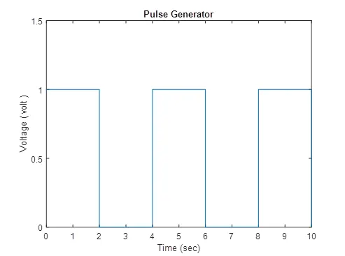
Fig3: Pulse Generator
The signal is drawn from the pulse generator to trigger the circuit. As per the objective the switch is to be closed for 2 sec and then released so we give input value time period 4 sec i.e. ON time + OFF time. The pulse width as 50% of pulse period. We get input as above image from Pulse Generator.
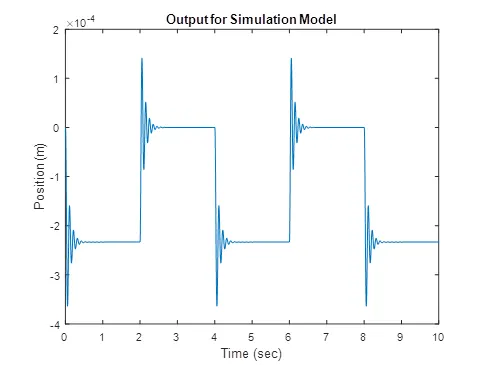
Fig 4: Output for Simulation Model (Spring Constant = 200, Damping =1)
When battery is ON current flows through the circuit and switch is closed for 2 sec. When current pass through the solenoid and plunger moves from port R to port C to hit the bell and producing the sound. Thephysical movement of plunger is sensed by the Ideal Translational motion sensor and physical output is converted into simulink output model is displayed in the scope. By reducing the spring constant value and increasing the damping value vibration will be reduced.
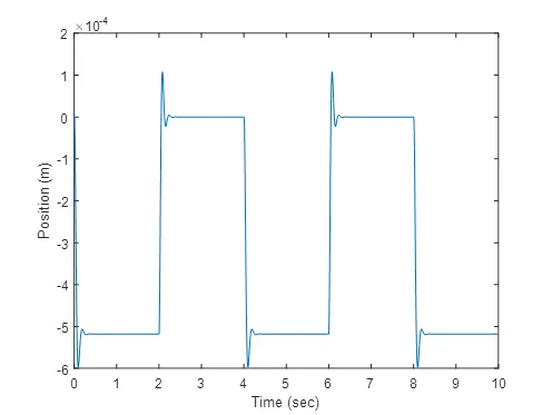
Fig 5: Output of Simulation Model (Spring constant = 100, Damping = 2)
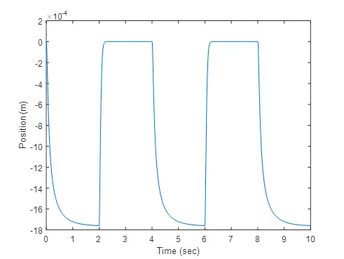
Fig.6: Output of Simulation Model (Spring Constant = 50, Damping = 3)
CONCLUSION
The doorbell model is created and executed. We observed that there is change in position of plunger when electricity is passed into solenoid.
SIMULINK MODEL USING THERMISTOR TO SENSE THE TEMPERATURE OF HEATER
AIM
Create a simulink model using thermister to sense the temperature of heater and turn ON & turn OFF as per given conditions. Run the simulink model as per given conditions and plot the results
OBJECTIVE
Given Inputs: Temperature source: 20 C from 0 to 10 seconds, 27°C from 10 to 30 seconds, 23°C from 30 to 50 seconds.
Fan conditions: ON if the temperature above 25°C, OFF otherwise.
EXPLANATION
In this simulink model first we need to find out threshold value of voltage at given condition of 25°C (298K ). This voltage value is given as threshold value ( 0.0119 V ) for switch condition. So input signal for controlled temperature source is created by using constant block ( Given value 298 ). 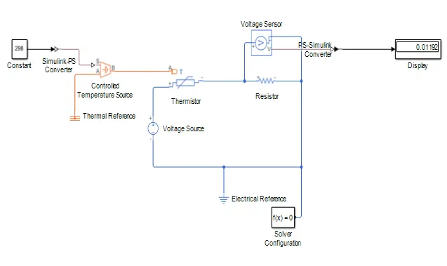
Fig1: Simulation Model for Threshold Value
- The requirement is such that the fan should be turned ON when temperature sensed is greater than 25°C. To fulfill this objective we use a voltmeter to find the voltage of circuit at different temperature. It is found that voltage at 25°C is approximately 0.0119 v.
- Now this voltage signal is passed through a switch. The switch is configured in such a way that, it is open if voltage across voltmeter is less than 0.0119 V ( temp less than 25°C ) and close if voltage across the voltmeter is greater than 0.0119 v ( temp more than 25°C ).
- The threshold of switch is set to 0.0119 V.
- From the switch output we can see that only output is between 10 – 30 sec as a temperature is greater than 25°C. So this output be given to fan for simulation.
A repeating sequence stair is used for input the values as per given conditions.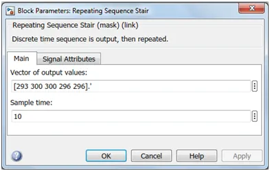
- Controlled temperature source represents an ideal source of thermal energy that can maintain a controlled temperature difference regardless of heat flow rate.
- The temperature difference is set by the physical signal ports. A positive temperature difference causes the temperature at port B to be greater than the temperature at port A.
- Thermistor is a type of resistor whose resistance is based upon temperature.Here we used NTC (Negative temperature coefficient) type thermistor. A linear resistor is used to convert the voltage measured between two points into a physical signal.Across the linear resistor voltage sensor is connected. Voltage source which represents AC or DC electrical reference block is given. We used DC voltage source i.e. 12V.
- Then we connect switch to display which is given 0.0119V threshold value. and this threshold value we have given to the switch. Again to the switch we connect two constant block (1 & 0). So that from 0-10 & 30-50 output will be turned OFF & 10-30 it will be turned ON.
- Solver Configuration: Each physical network represented by a connected simscape block requires solver setting information for simulation. Now we provide the motors parameter for getting optimum power output of the fan, then we connect a rotational motion sensor to find the angular velocity of motor. We connect scope to W port which represents angular velocity through simulink PS converter to get output result. Then we connect a reference for each of these.
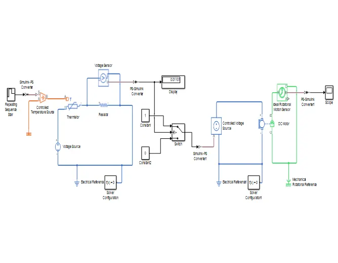
Fig 2: Simulation Model of Thermister to sense the Temperature of Heater
For 0-10 secs fan is in OFF condition, because temperature is 20°C (293 K) which is below 25°C (298 K). After 10 secs temperature goes to 27°C (300 K), so fan will turn ON, because temperature exceeds 298 K. After 30 secs fan will turn OFF because temperature goes to 296 K which is below 298 K. From the below results the given condition has been achieved and successfully executed.
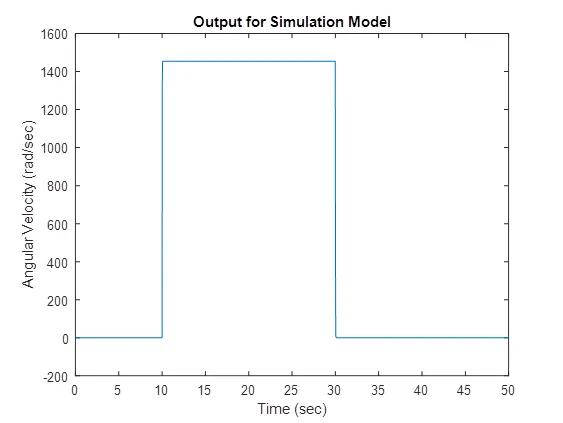
Fig 3 : Output for given Simulation Model
CONCLUSION
We have prepared a simulink model of thermistor to sense the temperature of heater and turn ON or turn OFF the fan. We also observed that the fan is turned ON when the temperature is above 25°C and turned OFF when the temperature is below 25°C.