Midsurface extraction and 2D meshing of plastic bottle cap in ANSA
Objective:
The objective of this project is to perform FEA preprocessing, i.e., geometry cleanup, midsurfacing, and 2D meshing for a plastic component with varying thickness. After meshing the component, PIDs with different thicknesses need to be assigned. The mesh should have a good flow and follow the following quality criteria,
| S.No. | Quality Criteria | Value |
| 1 | Target/Average length | 1 |
| 2 | Minimum length | 0.5 |
| 3 | Maximum length | 3 |
| 4 | Aspect | 3 |
| 5 | Warpage | 15 |
| 6 | Skewness | 45 |
| 7 | Jacobian | 0.7 |
| 8 | Minimum quad angle | 45 |
| 9 | Maximum quad angle | 135 |
| 10 | Minimum tria angle | 30 |
| 11 | Maximum tria angle | 120 |
| 12 | Tria % | 15 |
In this project, we will see the process of creating a 2D mesh for plastic components with varying thicknesses. For this purpose, ANSA software will be used.
Introduction:
2D shell meshing is performed for thin components so as reduce the long computational time during analysis. To do that first midsurface is extracted for the component. This is where it gets tricky for plastic components as they usually have varying thicknesses across the component with complex features like ribs. Therefore, midsurfacing needs to be done manually for each surface one at a time and then assign the PIDs/thickness individually to capture the geometry completely. And then meshing is performed for the extracted midsurfaces.
Procedure:
The plastic component for which preprocessing is done is a bottle cap, shown in the image below.
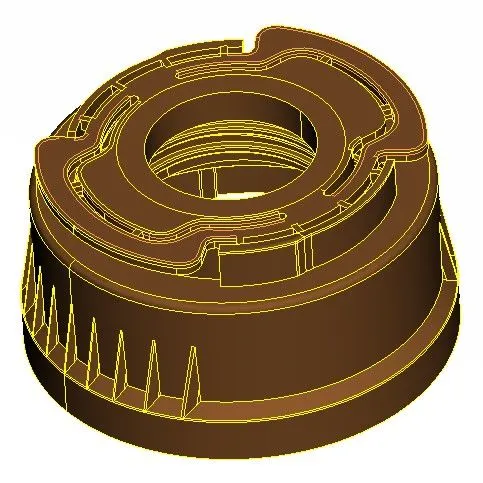
The first step after importing the model is to properly analyze and understand the geometry. This is important in order to plan for the midsurface extraction process and meshing. Also, When a CAD model is imported into the ANSA workspace, there might be several geometrical errors like missing/distorted surfaces, intersecting surfaces, etc due to the format conversion process or inherent bad model. And, it is important to clear all these errors before proceeding with midsurface extraction.
After analyzing the model, no issues were found with the geometry. To ensure that, geometry check is performed by going to Tools>Checks>Geometry. There were few small issues that were fixed automatically by right-clicking on the error>fix. Next, the orientation of all the faces is modified by going to Faces>Orient. This ensures that all the faces are oriented similarly.
The next step is to extract the midsurface for all regions and keep them in separate PIDs according to the thickness. First, auto-midsurfacing was tried by going to Faces>Mid-surface>Casting but it didn't produce proper results. So, all the midsurfaces were extracted manually. To extract the midsurface manually, Offset and Middle tools were primarily used. To extract the midsurface using the Offset tool first thickness of the region needs to be measured using the Utilities>Measure tool. After measuring the thickness, the surface on one side (preferably inner) is offset in the middle using the Offset tool by giving a value equal to half of the measured thickness.
Then, PID is assigned to the extracted midsurface by going to Faces>Set PID>Faces>New and under parameters, the original thickness is entered. This process is repeated for every midsurface extracted. And, for ribs with varying thickness, the average thickness was taken.
For outer ribs at the bottom, the Faces>Middle>Multi tool is used to extract midsurface as follows,
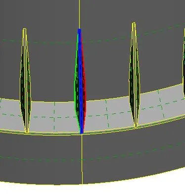
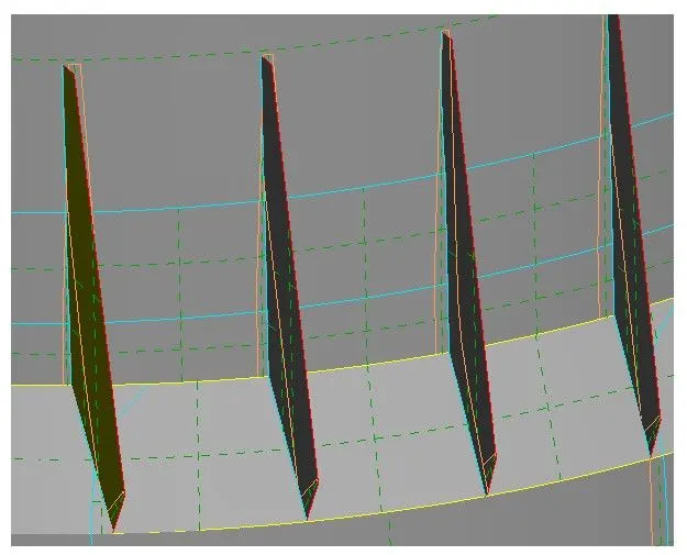
This tool automatically creates a PID and assigns the average thickness to the extracted midsurface. Then the created midsurface was extended and connected to the base surface like shown below,
Because of the method of midsurface extraction, extracted midsurfaces were not connected to each other and also needed geometry cleanup to delete or extend the surface accordingly. For this purpose, the Faces>Intersect & Faces>Extend tool is used.
To extract the midsurface of threads on the inner side, a curve is created in middle on the top face of the thread using the Curves>Middle tool as shown below,
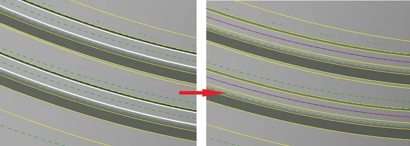
Lines highlighted in white are the lines used to create the curve and the purple curve is the created curve in middle. Next, the created curve is projected on the base midsurface using the CONS>Project tool to create a CON as shown below,
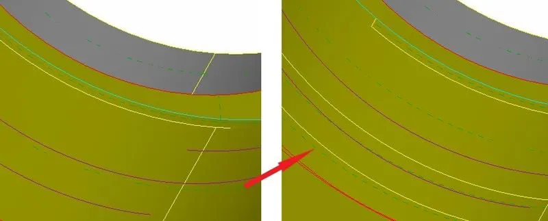
Next, a new surface is created using the Faces>New>COONS tool and selecting the newly created curve and the double CON. And the average thickness is assigned to the midsurface created. The image below shows the midsurface created.
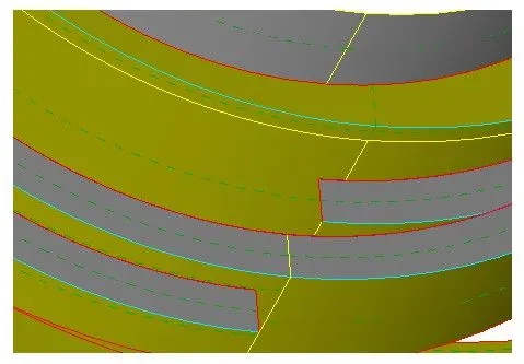
Next, there are teeth on the inner side like shown below,
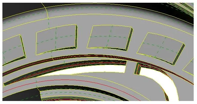
To extract midsurface for them, the top surface was offset by a value equal to half of the thickness at the front face like shown below,
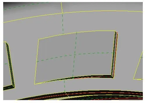
Next, to connect it to the base midsurface, the bottom edge was projected on to the base surface using the CONS>Project tool and then pasted together using the CONS>Paste tool, as shown below,
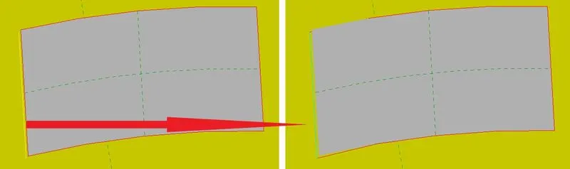
Finally, after extracting all the midsurfaces, it was checked for any geometrical issues and surfaces that were not connected were connected using the Faces>Topo tool. The images below shows the final midsurface model.
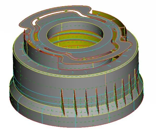
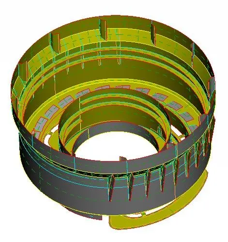
And the image below shows the PIDs created.
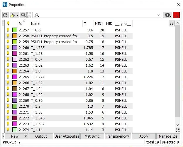
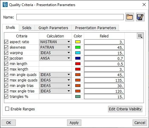
Now, before meshing, mesh parameters were configured according to the quality criteria by going to Utilities>Mesh Parameters. There, target length, minimum element length, and maximum element length are configured to 1, 0.5, & 3, respectively. All other parameters are kept as default for mixed and 1st order elements. Next, quality criteria were configured by going to Utilities>Quality Criteria. The image below shows the quality criteria created.
The next step is to prepare the midsurfaces for meshing. For that, switch to the Mesh module. First, the shell element length is altered by going to Perimeters>Length and all the CONS are selected and target element length 1 is fed as length value. The same is done for all the Macros (surfaces).
Next, all the areas are checked for minimum element length and altered ( if possible without altering the feature) slightly where elements might fail for minimum length. Similarly, CONS which are not essential to define a feature are removed by joining the surfaces using the Macros>Join tool.
Next, meshing is done using the Mesh generation>Best tool. This tool generates the mesh using the best algorithm applicable. Then, the created mesh is refined using the Shell Mesh>Reconstruct tool. It is ensured that there are no rotating quads. Also, trias are kept as low as possible. While dealing with trias, the following things need to be ensured.
- No back to back trias touching each other
- No opposite trias
- No trias touching the edges
- No trias on a feature
- Low concentration of trias in a region
To deal with trias, the following tools were used,
- Grid>Paste, to paste the nodes and move tria backward
- Elements>Split, to split an element and move tria forward
- Elements>Swap, to move the tria left or right
- Elements>Join, to join two trias to make a quad
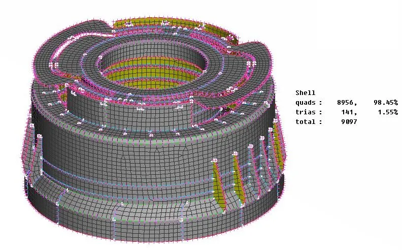
After modifying the mesh, Shell Mesh>Smooth tool was used to smoothen the flow of the mesh. Any elements failing for quality criteria were also fixed by either remeshing or smoothing the elements. The created mesh is shown below,
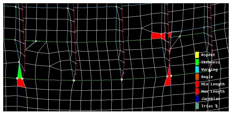
Then, the mesh is checked for quality criteria. There are a total of 14 elements failing and couldn't be repaired because they were constrained between two or more triple CONS, as shown below.
Finally, the shell element representation is changed by going to Utilities>Quality Criteria>Presentation parameters and enabling the 'Draw shell as solid' and ensured that the 2D shell mesh is capturing the geometry properly.
Conclusion:
Geometry cleanup, midsurface extraction, and 2D meshing of the given plastic component were successfully done. PIDs with different thicknesses were assigned accordingly. And all the elements pass the quality criteria except a few which couldn't be repaired due to geometric constraints. All the features in the model are captured properly with good mesh flow. Tria concentration is kept low at 1.55%.