Week 4
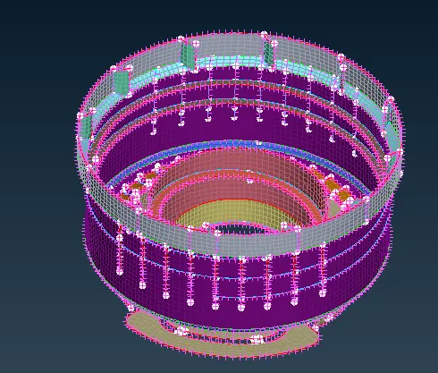
Aim: 1) To generate mid surface and meshing the component using appropriate element quality.
2) To assign the thickness and material to the component.
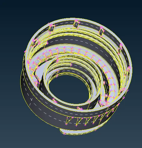
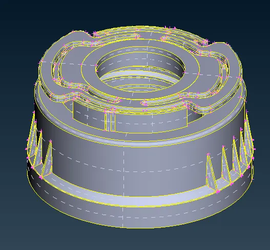
CAD model:
Procedure:
As the model is of plastic component the thickness may vary from surface to surface. It is advisable to check the thickness of every surface. As thickness is not uniform, the generation of the mid surface using manual method is used.
1) Generation of mid surface:
While creating manual mid surface, checking the thickness of the material and offsetting the face to the middle is important. The thickness of the surface can be check using different method depend on geometry and complexity of geometry
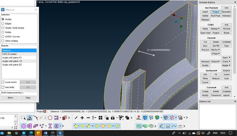
i) Measuring thickness on edge:
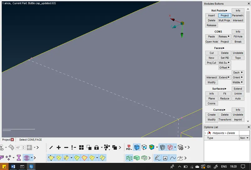
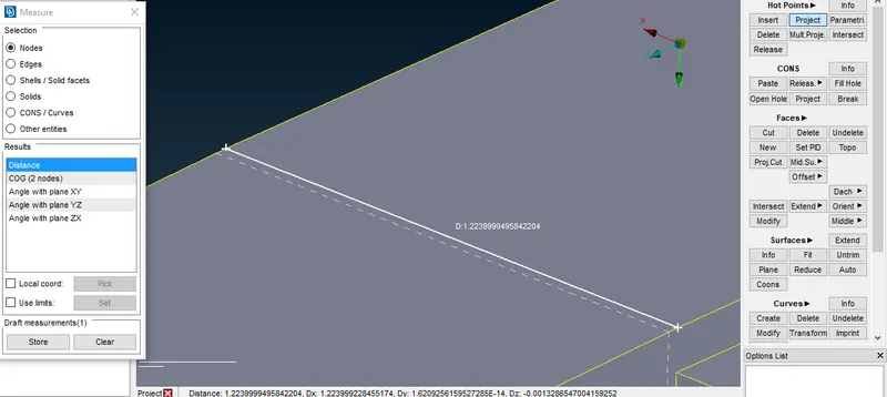
To measure the thickness on the edge, project hot point on con and then use measure hot point option
Topo – hot points – project – select point – select edge
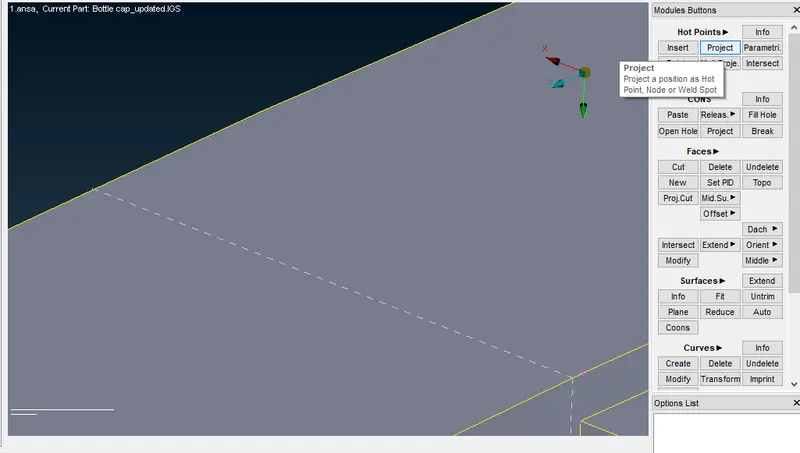
Utility – measure – hot points
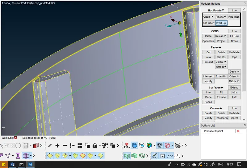
ii) measure thickness using weld point
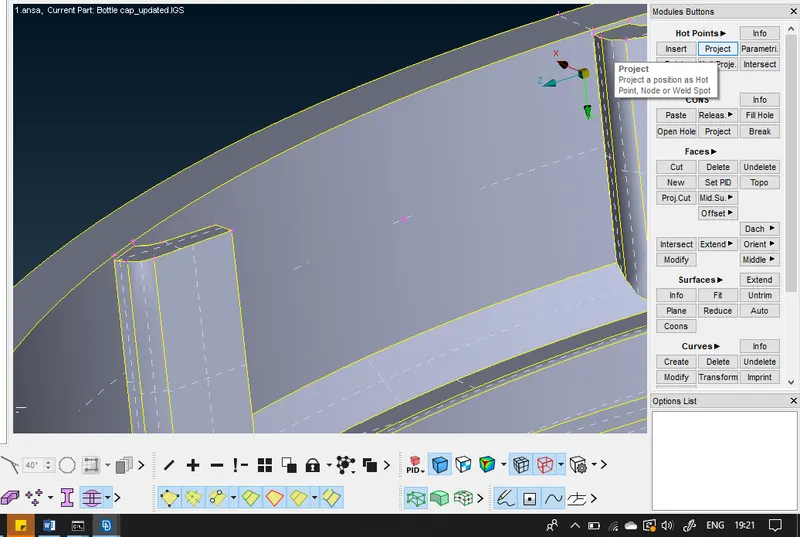
the surface which is complex to measure and be measured using weld point and project.
Topo – hot point – weld point – select surface
Topo – hot points – project – select point – select edge
Utility – measure – hot points
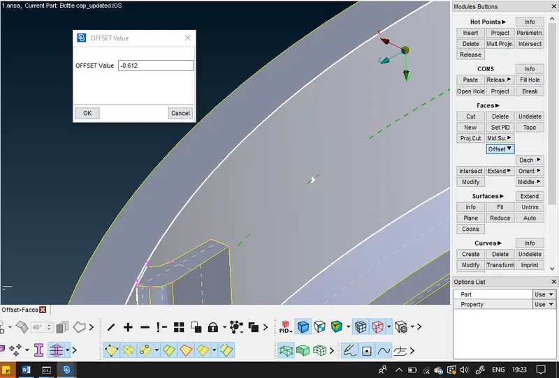
iii) offset the surface
Topo – Face – offset – select surface – distance
Once all the surface are extracted, check for geometry
This tool is used to connect the cons which are in tolerance limit. After generating topo the cons are categorized into three types
1) Single cons: which share 1 face, appears on the edges of the model, appear in red colour
2) Double cons: Shares 2 face, this type of cons are present within the model, appear in yellow colour
3) Triple cons: Share 3 face. It is advised to remove most of the triple cons, appear in blue.
If there is cut in between the surface than we can paste one con over another using paste option.
After completing the geometry clean-up check the geometry
Check manager - select parameter to check – execute
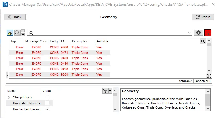
If there is any error we can manually resolve the error. In this model triple cons are necessary as the ribs are connected at single cons which makes it triple cons.
There are some surface having varying thickness in this case, using middle tool is suitable, as this tool will automatically generate mid surface.
2) Generating mesh on the mid surface:
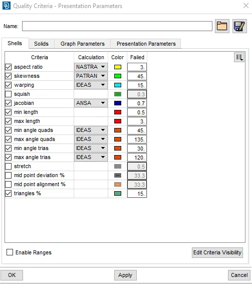
i) Changing the quality criteria
As the model should be meshed using different quality criteria, changing the criteria as per instruction.
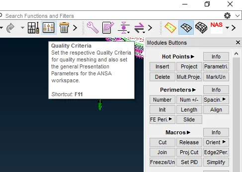
Go to Quality criteria or F11
Unlock the required parameter and edit it as per instruction.
ii) Change the mesh perimeter
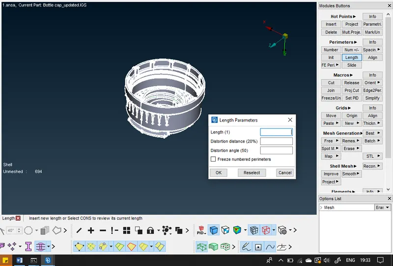
this is used to change the parameter like mesh flow, element size, element order, element shapes
Change the length of the perimeter to 1 as the element size is 1
Mesh – Perimeter – Length – 1 – select all
iii) Meshing the model:
In ansa, we can mesh model using a different algorithm, as per geometry. We are going to use the best option as it will select the best suitable algorithm for meshing the component. After meshing the model use reconstruct the mesh using reconstruct option, this will improve the mesh flow and reduce the tria in the region, even if the mesh is to reconstruct use split option to move tria and to combine trias.
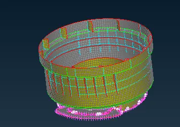
After reconstructing the mesh flow get disturbed, to create good flow mesh use option of smoothing operation. This improves the mesh flow.
iv) Check the quality criteria of element :
to check the failing element unlock the hidden view option. This tool will display the failing element due to different parameters.
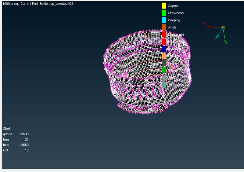
Try to eliminate elements using reconstructing, smoothing, moving trias, etc..
In this care if we try to remove failing element, the geometry may disturb, in such case we can leave it as it is.
3) Assign the Property ID
As the model is of plastic component it may have varying thickness, for each thickness we have to create different properties for different thickness.
Before assigning the property ID we have to create the property
To create property ID
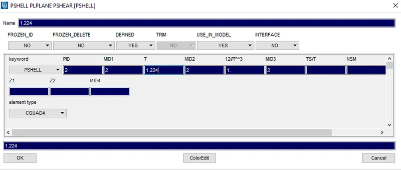
List – property – right click – create one – assign thickness
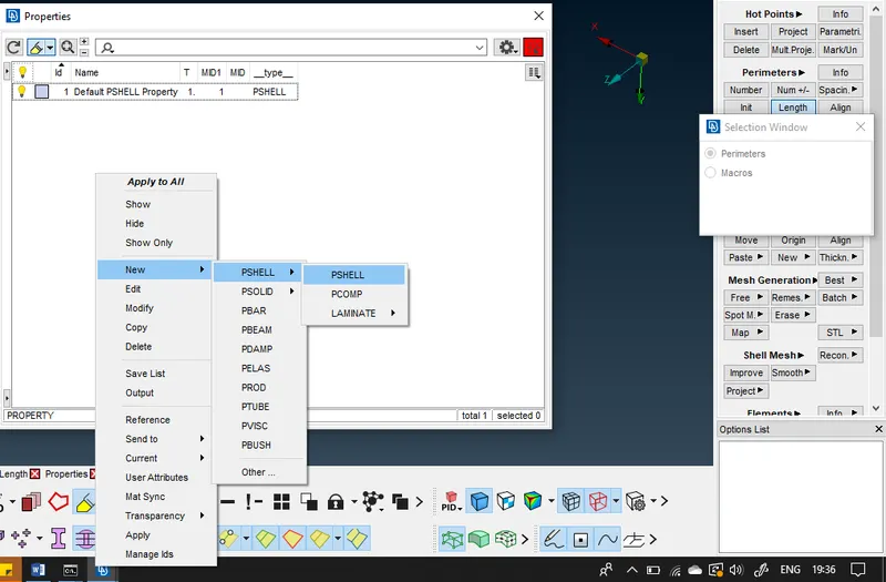
Create property according to the thickness variation
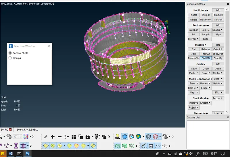
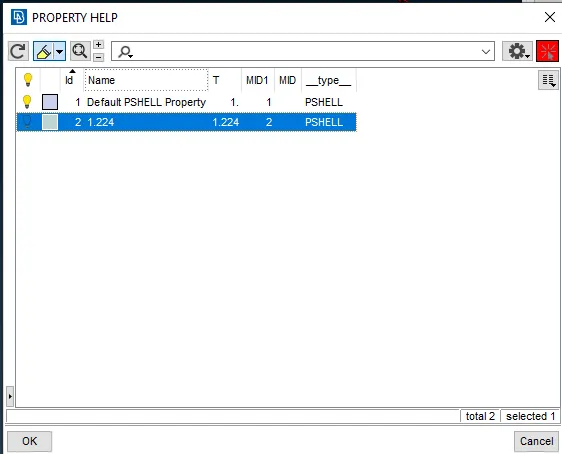
After creating property ID, assign the geometry to property ID
Mesh – Macros – Set PID – select face – select PID
Conclusion:
- Got to know the interface of ansa software, learned how to clean up the geometry, mesh the component and hot to eliminate the failing elements.
- Got to know property ID and associated steps while assigning property ID to the geometry.
Final model: