Week - 4
AIM: To implement control logic of washing machine using stateflow.
To make simulink chart for the gear shift.
WASHING MACHINE :
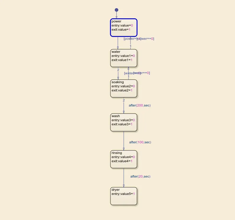
fig 1
* The above image represents washing machine model in simulink. The system works according the initial conditions of power and supply. When there is a power , the water is supplied and next processes like soaking,washing,rinsing and drying take place. The input conditions 1&0 represents the ON and OFF of system.
* In the above system the soaking process takes place for 200 seconds , washing takes place for 100 seconds , rinsing takes place for 20 seconds and finally drying takes place.
* The entry value is set as 0 and exit value is set as 1 .
* When the values of power and water supply are 1 then the output of all processes will be 1.
* When the values of power and water supply are 1&0 respectively the water is not supplied and output becomes 0.
* When both the values of power and water supply are 0 then the system does not work and output is 0.
* In the following pictures the display block is connected to 6 outputs to denote the working condition with respect to inputs.
* Two constant blocks are connected to power and water supply which decides the system's working condition.
* Lamp is connected with power and water supply and denotes the working condition. When the input is one ,the system works and green light is used to indicate former(ON condition) . When value is 0, red light is shown which denotes the OFF condition of system.
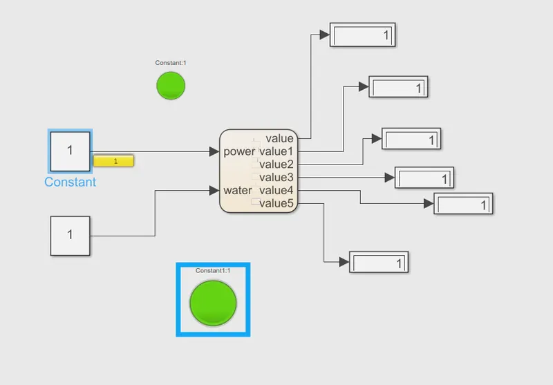
fig 2 (the system is turned on and all the processes take place successfully as initial conditions are 1)
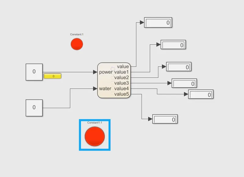
fig 3 ( the processes are terminated as initial conditions are 0)
GEAR SHIFT :
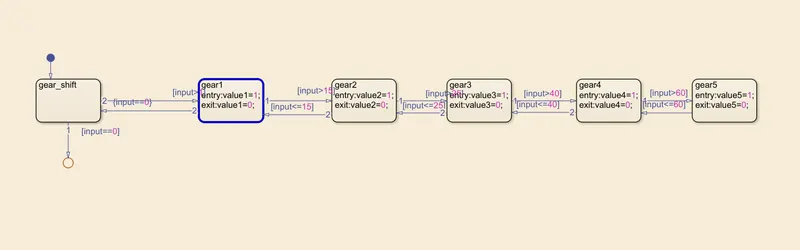
fig 1
* Above figure represents the gear shift system. When the initial condition given more than 0, the gear shifts to 1 and followed by other conditions.
* The initial condition denotes the speed of the system. As the speed increases the shifting of gear also increase with respect to following conditions ,
Speed Range(kmph) Gear
0 to 15 1
16 to 25 2
26 to 40 3
41 to 60 4
Above 61 5
* When the there is a decrease in speed , the gear shift process flows in backward.
* The entry and exit values are set as 1&0 respectively.
* The display blocks and slider gain are used to display output and input respectively.
* Stop time is set as infinity.
* 1&0 used to denote ON & OFF conditions respectively.
* In the following figure , the initial condition (speed) is set as 7kmph using slider gain and corresponding shift takes place and value 1 is displayed in gear 1. This means that gear 1 is currently working while other gears 2,3,4&5 remains stopped.
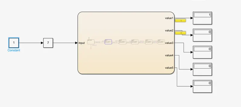
fig 2
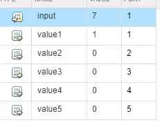
fig 3 ( input and output is set in symbols)
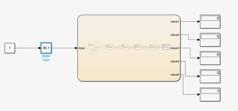
fig 4 ( here the speed is set as 65.1 and as it is more than 60 ,the 5th gear is in use)
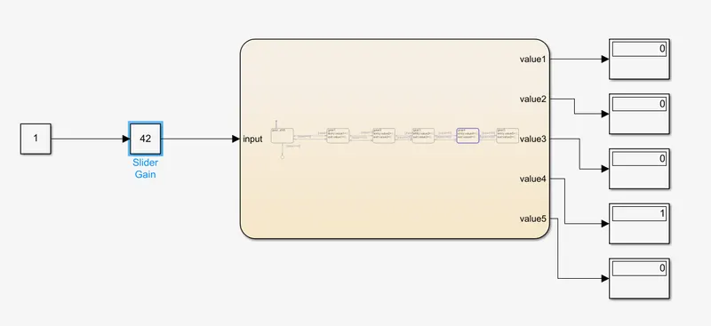
fig 5 (here the speed is set as 42 and as it is more than 40 , the 4th gear is in use)