Week 4.1: Project - Steady state simulation of flow over a throttle body
Introduction:
A valve designed to regulate the supply of a fluid (as steam or gas and air) to an engine and are operated by a handwheel, a lever, or automatically by a governor. Especially : the valve in an internal-combustion engine incorporated in and are regulated for controlling the volume of vaporized fuel charge delivered to the cylinders.
A throttle is the mechanism by which fluid flow is managed by obstruction of a throttle.
An engine's power can be increased or decreased by the restriction of inlet gases (by the use of a throttle), but usually decreased. The term throttle has come to refer, informally, to any mechanism by which the power or speed of an engine is regulated, such as a car's accelerator pedal. What is often termed a throttle (in an aviation context) is also called a thrust lever, particularly for jet engine powered aircraft. For a steam locomotive, the valve which controls the steam is known as the regulator.
In an internal combustion engine, the throttle is a means of controlling an engine's power by regulating the amount of fuel or air entering the engine
To regulate the power output from an engine there have to be some restriction of how much fuel - air mixture that reaches the cylinders. One way to do this is to use some kind of valve that restricts the air, fuel is then regulated to get the correct fuel - air mixture.
Objective: To perform a steady state simulation in a an elbow consisting of an throttle body in it in order to analyze the flow parameters and the fluid behaviour in the vicinity of the nozzle inside the throttle body.
Process:
The Geometry of the elbow was imported in Converge as an stl file and was checked for proper dimensional units.
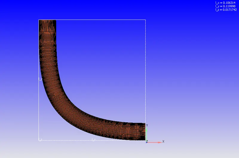
Elbow body
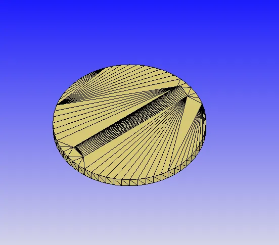
Throttle body
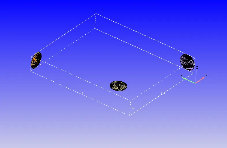
Throttle body with Inlet and outlet
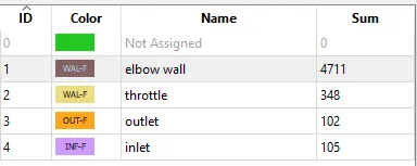
Boundaries were created namely, elbow wall, throttle, inlet and outylet and proper Boundary conditions were assigned to them according to requirement.
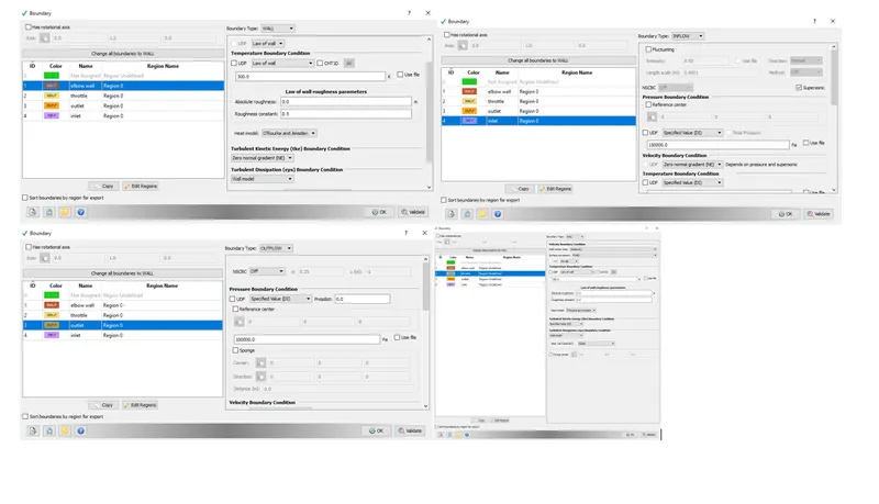
Boundary conditions: Elbow(Boundary Id 1) and throttle were assigned WALL boundary type with wall motion kept as stationary for both as it is a steady state simulation. Inlet(Boundary id 3) boundary type inflow and pressure =150000 Pa, species inflow O2 and N2. Outflow (Boundary id 4) boundary type outflow and pressure=100000 Pa, Species :- O2 and N2. All boundaries are assigned Region 0.
Application: General Flow
Material: Gas simulations and Global Transport propertiers were set as default.
Regions and initialization: Temperature 300 K, and pressure= 101325 Pa, Species Air (O2 and N2).
Physical modeling: Turbulence modelling with RNG
Run Parameter under the Simulation Parameter

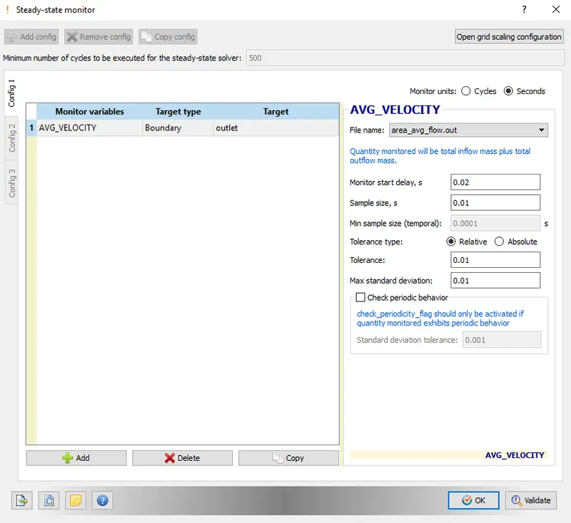
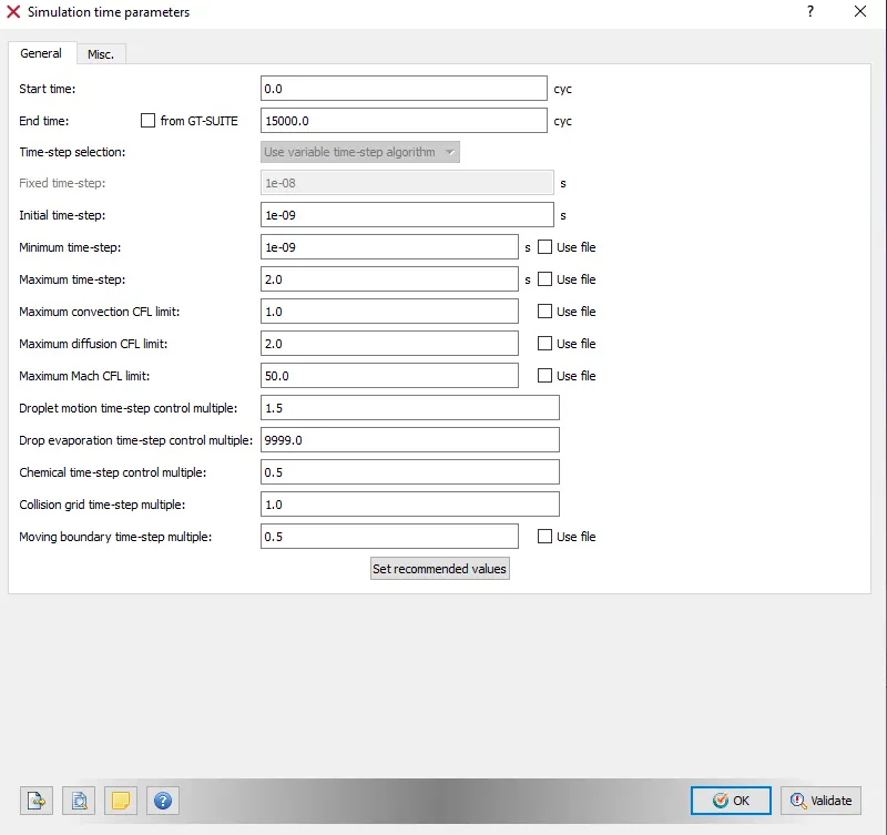
Steady state pressure based solver was chosen under the solver tab, flow mode was set to the Full Hydrodynmic under the simulation mode and Compressible flow was chosen under the Gas flow solver. In the Miscellaneous tab, steady state monitor was checked on and use shared memory was unchecked because sterady state simulation is performed.
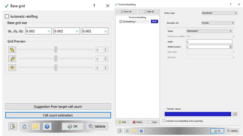
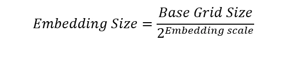
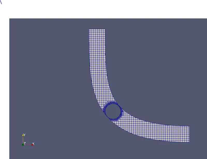
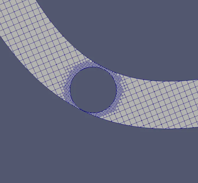
Fixed embedding is applied to refine the grid at specific locations in the domain where a finer resolution is necesasary for the accuracy of the solution. Fixed embedding allows the rest of the grid to remain coarse to minimize simulation time. For each fixed embedding, one must specify an embedding scale that indicates how CONVERGE will refine the grid in that location(here in this case the vicinity of the throttle valve). The embedding embed_scale parameter in embedded.in, which must be a positive integer, scales the base grid sizes according to the formula
- Post Processing of Results
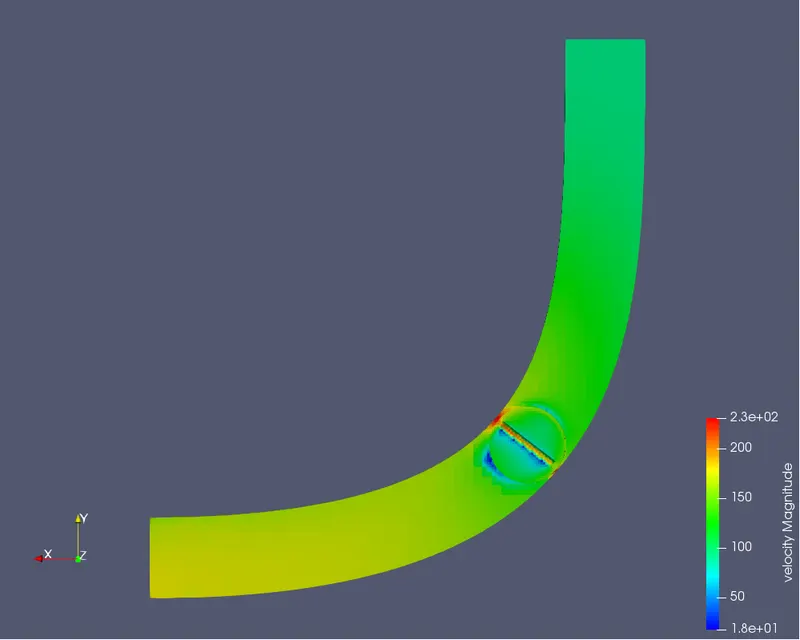
The top part is the inlet and the bottom is the outlet side, We can see the velocity at steady state in final iteration is more towards the outlet, as this valve is open. The valve geometry is not exact to scale and hence there is flow from the top and bottom. The maximum velocity reached is 270 m/s.
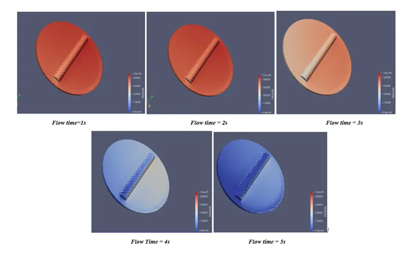
Variation of Pressure in the throttle body
On the throttle, we also observe the two region which is red and blue. Red colour shows the high pressure region and blue colour shows the low pressure region. In high pressure region fluid impose the pressure on the throttle as it flows over the throttle body. And the low pressure region(blue region) is due to the flow separation happening near the axis of rotation of the throttle
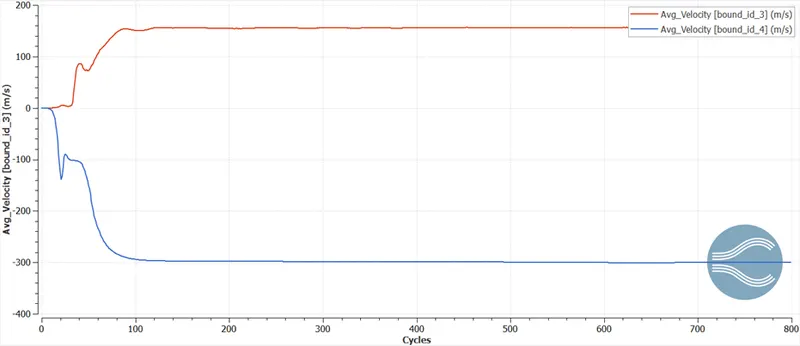
- Plot for average velocity at the inlet and outlet:
The positive velocity represents the inflow while negative velocity represents the outflow. Here we are observing the average value the elbow with throttle valve fully open achieves. The inlet velocity is dropped to nearly -300 m/s while outlet is above or near to 150 m/s.
- Plot for Mass Flow rate( mass is conserved between the inlet and outlet)
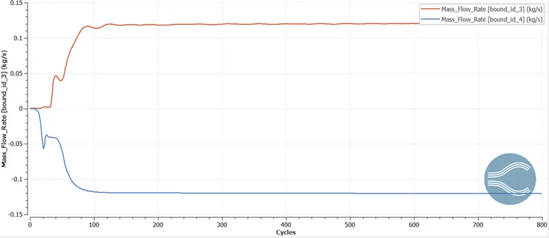
- Plot for static pressure and between inlet and outlet
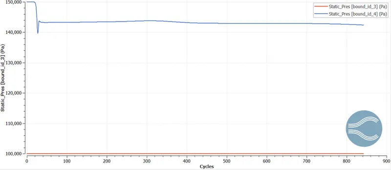
Since the inlet and outlet is open to atmosphere the static pressure difference is constant.
- Plot for Total Pressure and Static pressure at the inlet and outlet
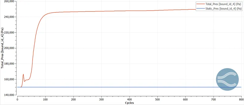
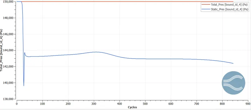
At the inlet, we observe that initially total and static pressure is same which is 150,000 Pa. And since total pressure = static pressure +dynamic pressure and initially dynamic pressure is zero. As the simulation runs with cycles the static pressure is going to decrease due to increase in dynamic pressure. After nearly 850 cycles the static pressure is going to decrease rapidly due to fast movement of fluid. Finally at the outlet the static pressure reaches to 142,000 Pa and the value of the total pressure is increases to 245,000 Pa in the inlet and is constant at the outlet due to increase in dynamic pressure.