Week 4.1: Project - Steady state simulation of flow over a throttle body
AIM:
- The aim of the project is to simulate the flow through a throttle body. The objective is to understand the development of the flow with the aid of different plots.
THEORY:
-
The throttle valve arrangement which is the subject of this analysis is frequently used in automobiles to regulate the air-fuel mixture in the combustion engine. Butterfly valves are the most commonly used valves. In this analysis, we would be examining the results under the assumption of a steady state. Throttling is an Isenthalpic process.
A.CASE SETUP:
1. Geometry Creation:-
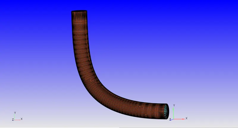
- The geometry that was used for the analysis is shown below. An STL file was imported into CONVERGE. It comprised a number of open edges that were cleaned using a Patch command.
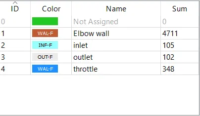
- Creation of Boundaries: In the geometry which is created above, boundaries such as inlet, outlet, outer body and throttle.
- Checking Orientation of Normals: The orientation of Normals was checked to ensure all the normals are pointing inwards. This was done using the Normal Toggle
- Finally, a Diagnosis check was run to ensure no errors in the geometry.
B.CASE SETUP:
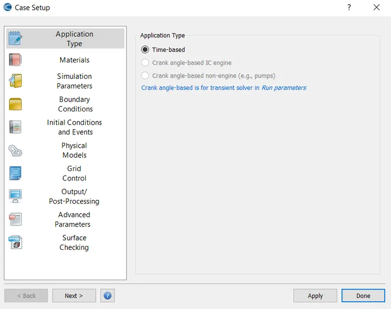
- Application Type:- This was set to Time based,
2. Materials:-
- This was set to Air, Gas Simulation: Default properties were retained.
- Global Transport Parameters:- Default properties retained
3. Simulation Parameters:-
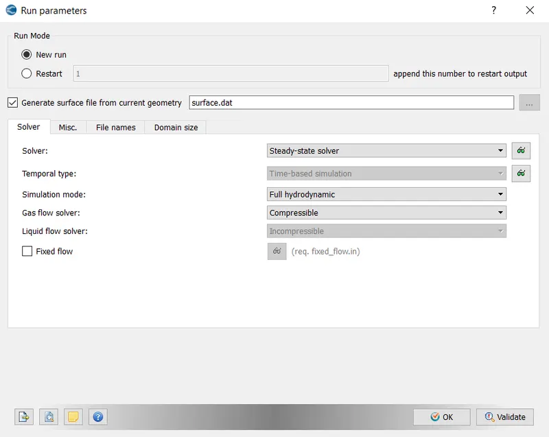
- Run Parameters:- Steady state solver was used. The simulation mode was set to Full Hydrodynamic. The gas flow solver is set to Compressible
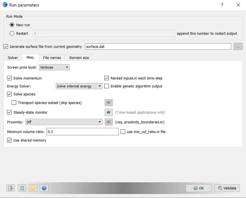
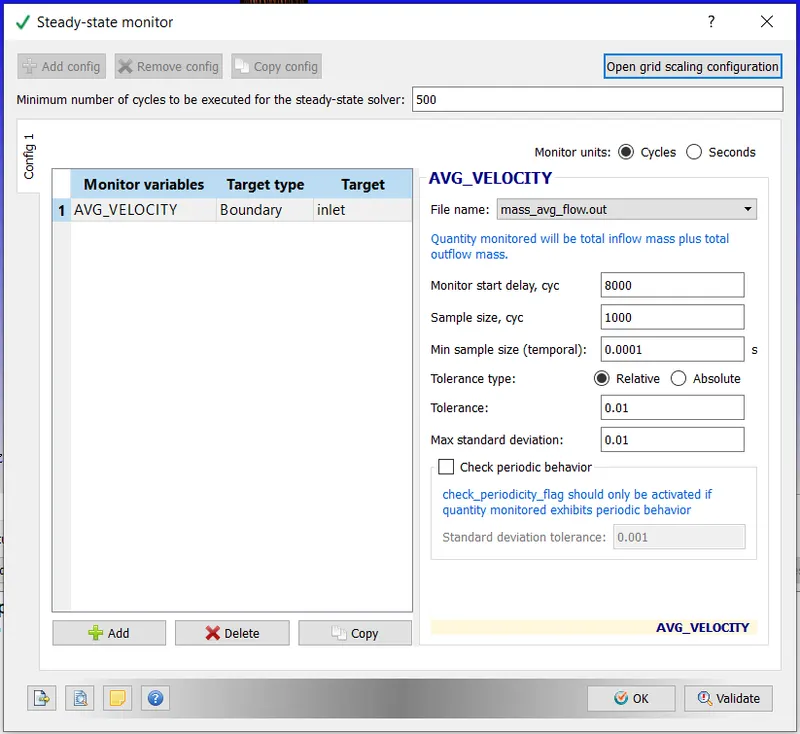
- Steady State Monitor:- Minimum no of cycles to be executed for Steady-state solver -500
Monitor Start Delay, cyc:- 8000
Sample size cyc:- 1000
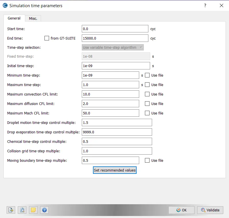
- Simulation Time Parameters:- The parameters were set as displayed below. Max CFL limit set to 1.0,
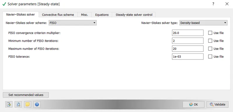
- Solver Parameters:- A Pressure based PISO solver was used, Maximum Convection CFL limit was set to 0.5.
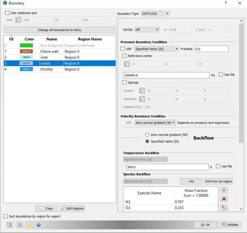
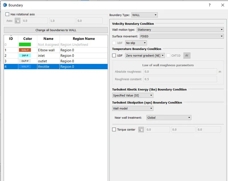
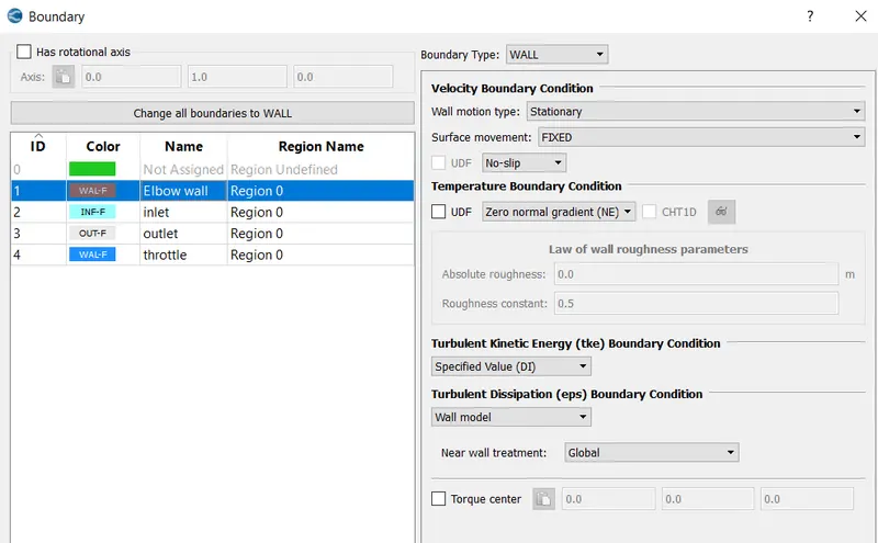
- Boundary:
- Inlet:- Boundary flow - Inflow
Inlet Pressure- 150000 Pa
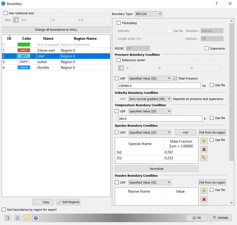
- Outlet- Boundary - Outflow,
- Throttle:-
- Elbow Wall:
- Initial condition and events: The created geometry was selected as the Volumetric Region,
- Physical Models:- Default retained,
- Turbulence Modelling:- RNG-epsilon turbulence model is used,
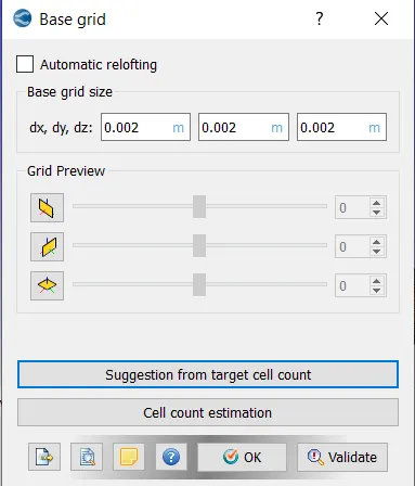
- Grid Control:- A Grid size of 0.002 is entered in the dx,dy and dz directions,
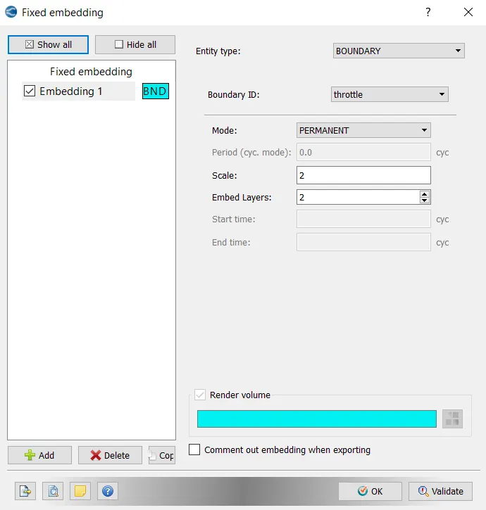
- Fixed Embedding was also enabled. This was done to capture the flow around the throttle valve with greater precision.
- Output/Post Processing:- The variables that we intend to see during post-processing are selected. In this case, Density, Pressure, Temperature and Velocity were selected.
- After setting the above, the input files were exported to a directory
- In order to execute the simulation, the directory in which these input files were stored was accessed in Cygwin and the following command was typed "mpiexec.exe -n 4 converge.exe"
- After the Simulation was executed, the results were converted into a form which would be compatible with Paraview. This was done using the post_convert.exe command.
RESULTS:
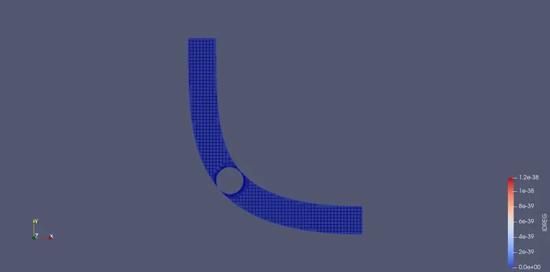
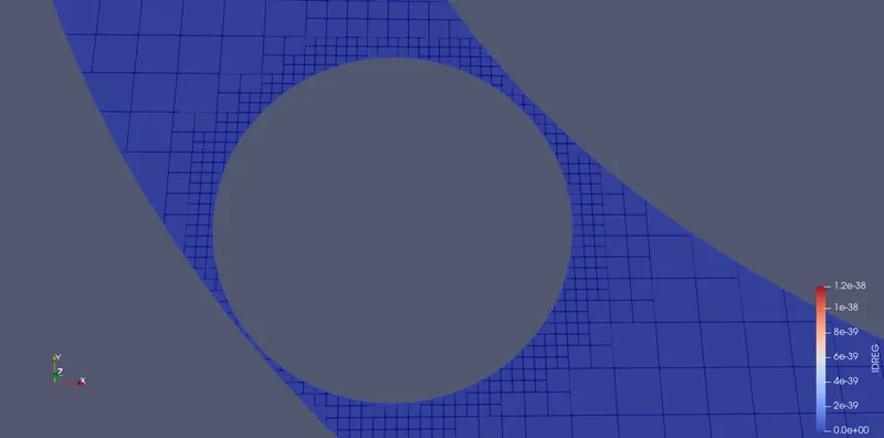
MESH VIEW:
1) A Slice cut out with normal in the Z direction is given below,
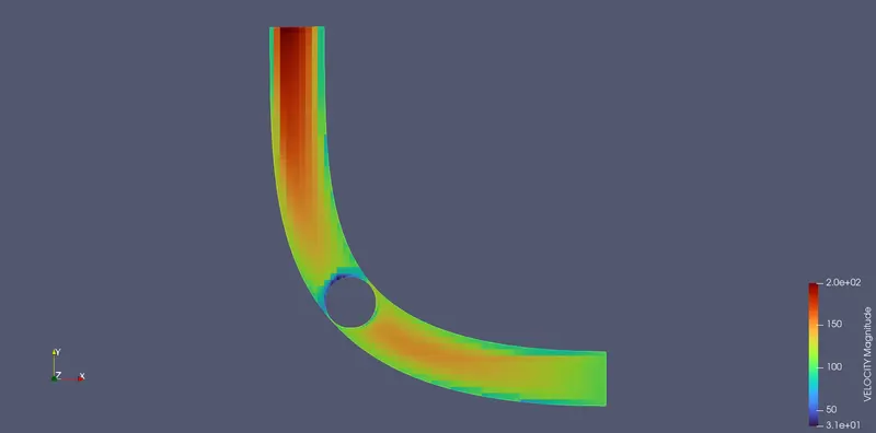
2) Velocity Contour:
2) Pressure Contour:
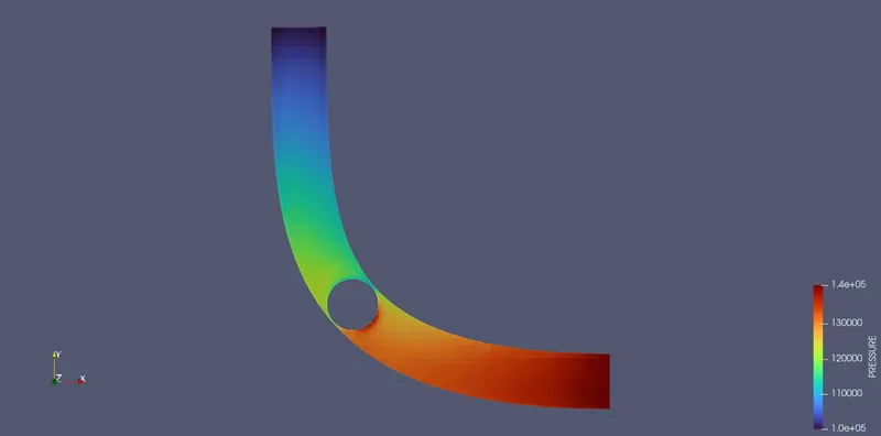
- From the above plots, it is observed that no significant pressure drop is encountered across the throttle.
PLOTS:
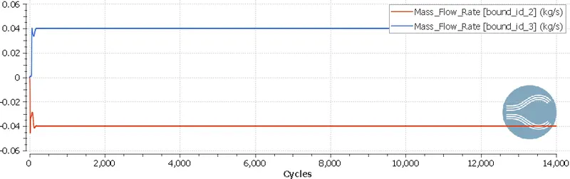
i) Mass Flow Rate:
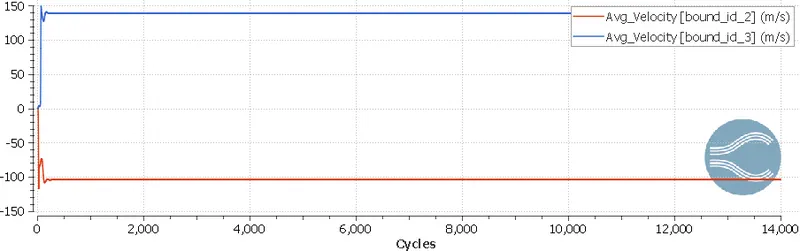
ii) Average Velocities:
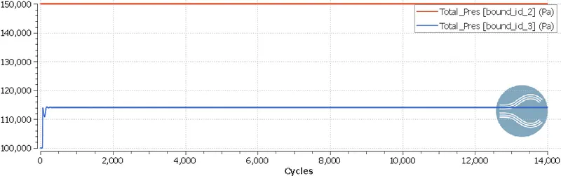
iii) Total Pressure:
-
From the above plot it is seen that while the inlet pressure is constant at 150000 Pa, the outlet Pressure reaches a value of a little below 120,000 Pa after 2000 cycles.
-
From the above plots, we observe that the values for mass flow rate, average velocity and total pressure attain convergence after 2000 cycles.
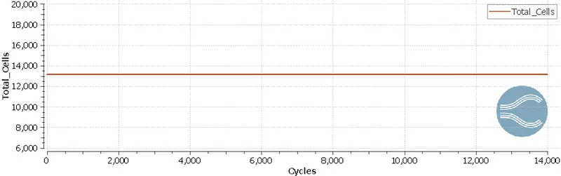
iv) Cell count:
CONCLUSION:
- It is observed that the solution reaches a steady state at 2000 cycles. No significant pressure drop is encountered across the throttle.