Week 3 Verification of Weld Joints
Objective
To perform a static analysis for the model with welded joints using different materials and to compare the results.
Case 1.
Stainless Steel: In this case, the material of the plates must also be the same. Use Stainless steel for both weldments and plates. No need to add flux to the weldments.
Case 2.
Aluminium Alloy: The material to be chosen for this case is Aluminium alloy(high strength, wrought). [Plate material to be used is stainless steel]
Case 3.
Bronze: In order to simulate "Brazing", you should be using bronze as the weld material. Assign Stainless Steel to both plates and Copper to the "Ribs".
Procedure
- A new Ansys file was opened and dragged the static structural module onto the project window.
- The model was inserted in the geometry tab and opened the space claim to see any abnormality exists within the model. if there is any correction has to be made.
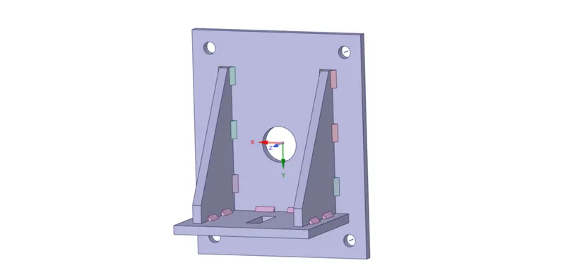
- Open the module tab to undergo further setup. From the geometry option, we could see lots of parts and it's been renamed accordingly.
- Material
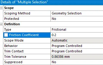
- Now go to the contact tab, right-click>re-name based on the definition. The contact between the big plate, small plate, and the rib is frictional other than the welded joints which will be bonded. Select all the five pairs that were just mentioned which contain the contact between the big plate, small plate, and changes were made as shown below.
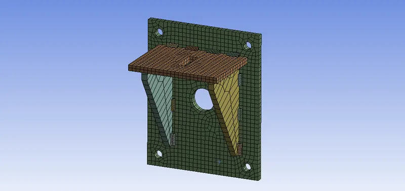
- Select the small and big plate using the solid filter and go to the mesh tab, right-click>insert>sizing. Sizing of 7mm was done and generated the mesh.
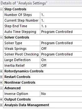
- For the analysis setting up the large deflection was turned 'on' because if we move to the non -linear region, we will be able to capture the non-linearities in the model.
- If we look at the geometry of the model, it's going to fix on the wall by bolted joints and the load is provided to the hole as shown below.
- To fix the geometry, right-click static structural>insert>fixed support and selects the surfaces shown below.
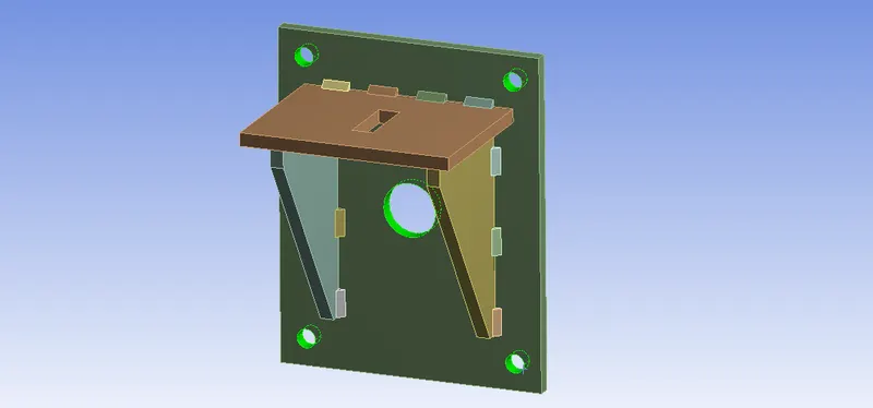
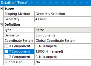
- The required force was inserted by right-clicking static structural>insert>force. Select the surface of the rectangular hole as shown below and assign a load of 12000N which is acting along the y-direction.
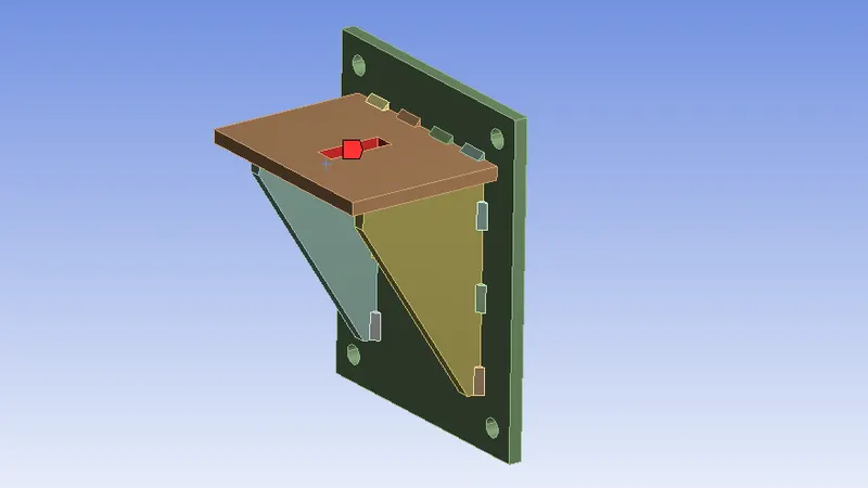
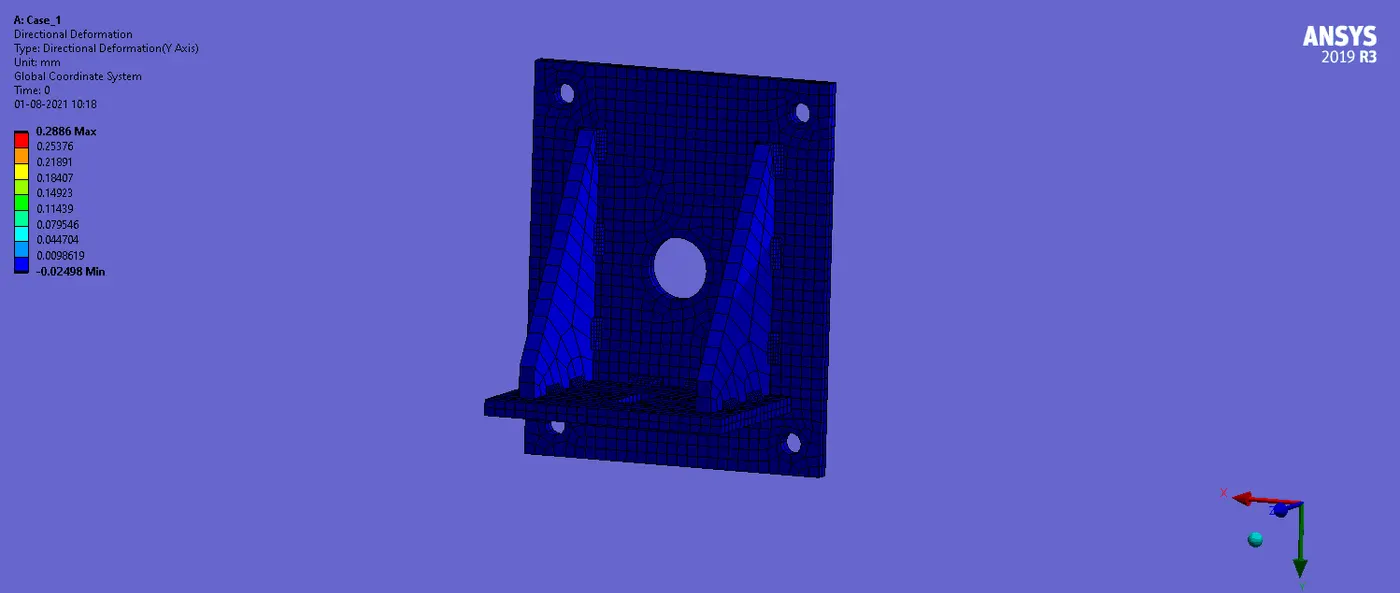
- From the solution, the output for the simulation was requested. Since the deformation happens in the y-direction, it's assigned by right-click solution>insert>deformation>directional, and change the orientation to the y-axis.
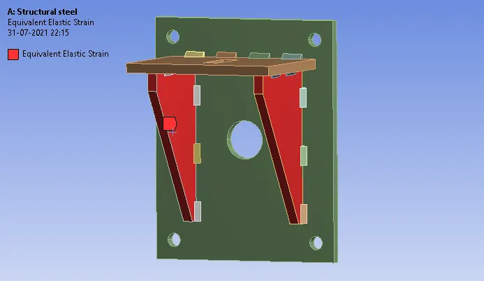
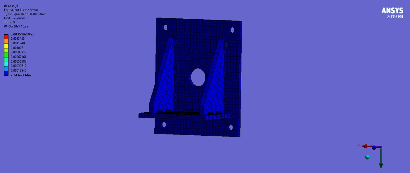
- Again, from the solution, the equivalent elastic strain was requested, and to observe the strain around the ribs we may select the two ribs using the solid filter.
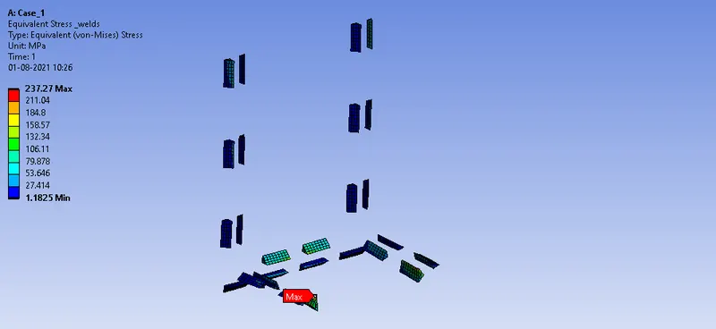
- To observe the stress-induced at the welded joints, right-click solution>insert>equivalent stress, and select all the welding joints.
- After providing the required parameters for the out-put, click solve.
- The same procedure was followed for case 2 and case 3, by changing the material types.
Results
- Static structural analysis for the model with welded joints using different materials was performed and satisfied all the objectives. The results got from the simulation are discussed below.
- The below results show the outputs from the simulation for case1. The shown was run at an autoscale of 60. To see the actual one it can be changed to true scale.
Directional deformation (Along the y-axis)
Equivalent elastic strain
Weld joint which experiences the highest equivalent stress
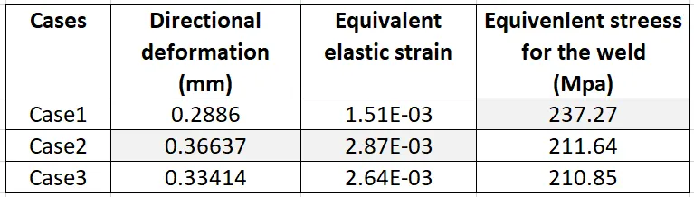
- Similarly, the results for other cases were also found and tabulated for comparison.
Case 1.
Stainless Steel: The material of the plates is the same. Stainless steel is used for both weldments and plates.
Case 2.
Aluminium Alloy: The material to be chosen for this case is Aluminium alloy(high strength, wrought). [Plate material used is stainless steel]
Case 3.
Bronze: Bronze is used as the weld material. Stainless Steel for both plates and Copper to the "Ribs".
- From the table, it can be inferred that the model, done using the case 2 material that has got the maximum directional deformation and the equivalent elastic strain and case 1 shows the minimum value.
- The equivalent stress for the weld is maximum for case 1 modeled with stainless steel and case 3 has the minimum equivalent stress for the weld that was modeled with cast bronze. So as per the design point of view, the bronze material can be considered as the weld material since it has the least stress values among the list.
.............................................................................................................................................................................................................
File: https://drive.google.com/file/d/14zh-QP2zLKjhGvSJSnKnejJHuL3rmkY6/view?usp=sharing