Week 3 Verification of Weld Joints
REPORT
VERIFICATION OF WELD JOINTS
OBJECTIVE
To perform static structural analysis on weld joints using three different materials and to find out directional deformation, equivalent strain and weld joint that experience maximum stress in each case.
PROCEDURE
CASE 1
The model is opened in mechanical module.
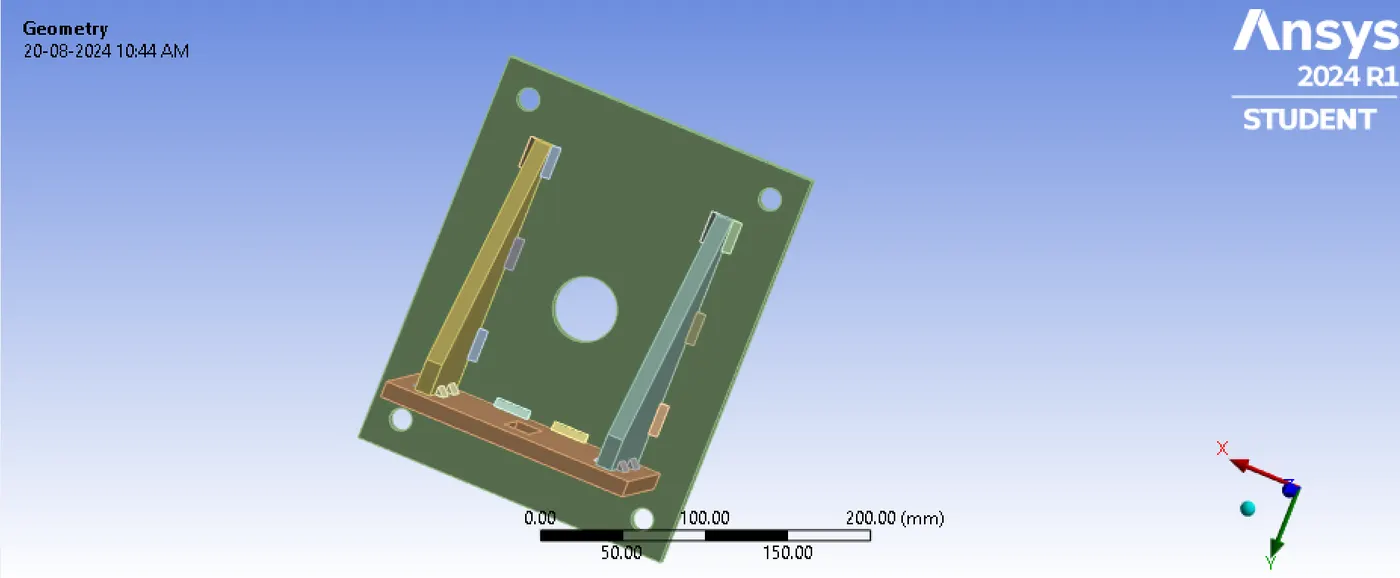
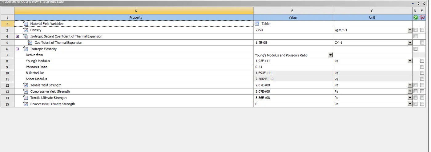
For case 1, the materials using in weld joints and two plates are stainless steel. The properties of the material is tabulated below,
For the ribs, structural steel is assigned and its properties are given below,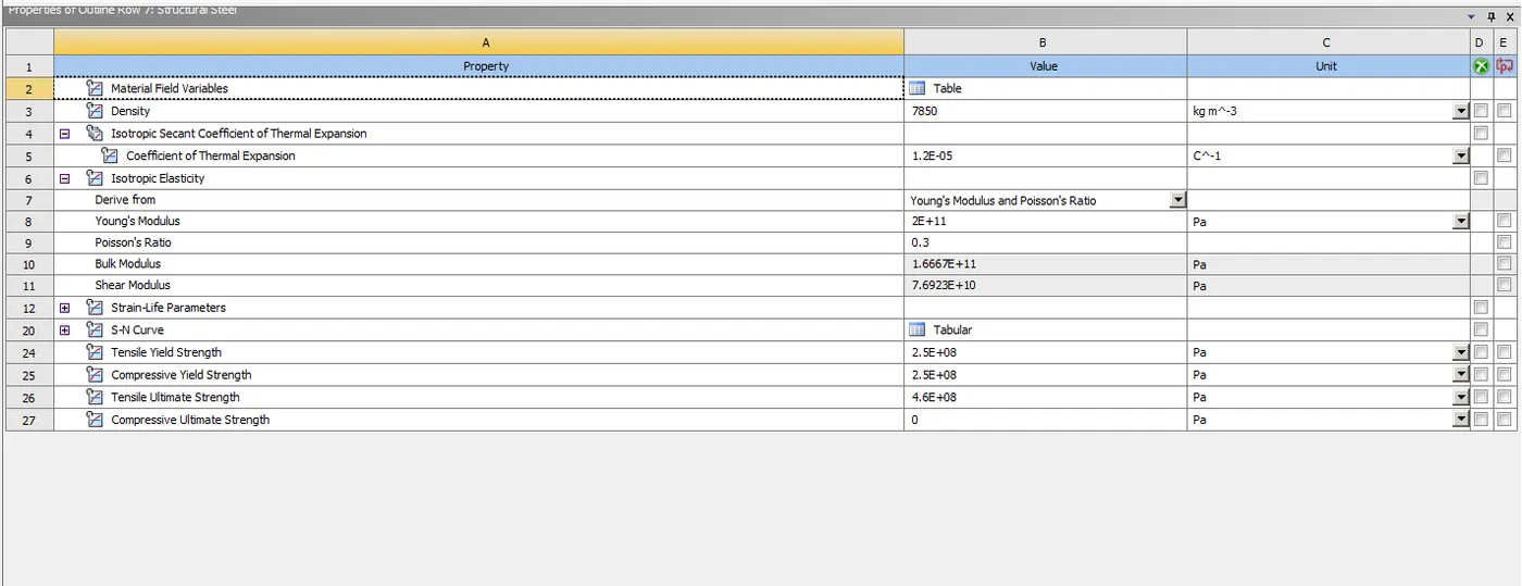 The contacts between all the weld joints are bonded. The contacts between the plates and the ribs are frictional and a frictional coefficient of 0.2 is assigned.
For mesh, a 12mm mesh is given to ribs and a 7mm mesh is given to plates.
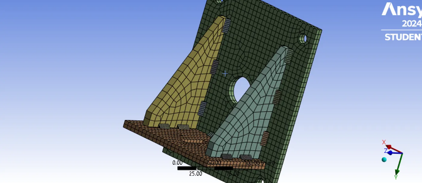
Large deflection is set ON in analysis setting.
STATIC STRUCTURAL
The large is fixed using the five holes in the large plate.
A force of 15000N is applied in the rectangular hole in the small plate(Y DIRECTION).
SOLUTION
Requested for
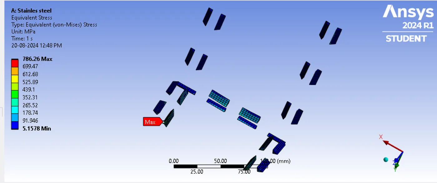
1. Equivalent stress in all weld joints.
2. Directional deformation
3. Equivalent stress experienced by the setup.
RESULTS
Equivalent stress
Total deformation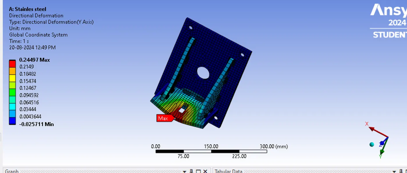
Equivalent elastic strain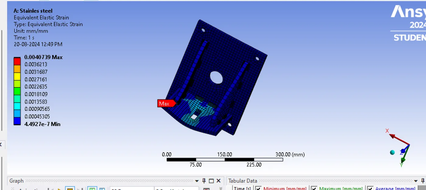
CASE 2
In case 2 materials used is different
For the weld joints aluminium alloy is used, the properties of the material is shown below,
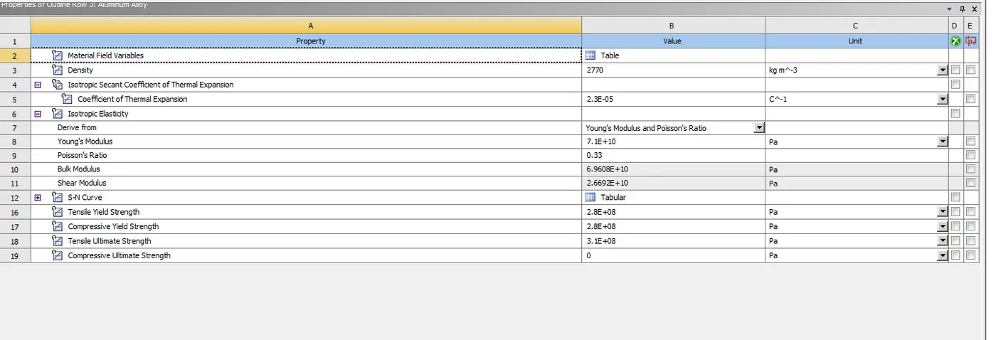
For the plates, stainless steel is used and structural steel is used for the ribs. All other procedures are same as case 1.
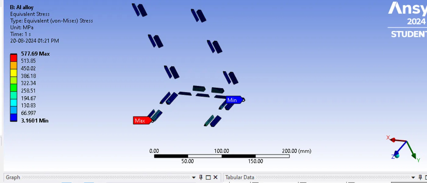
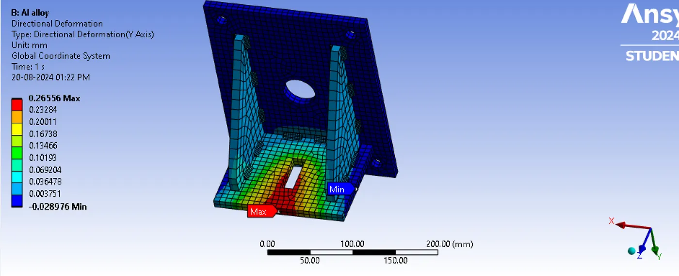
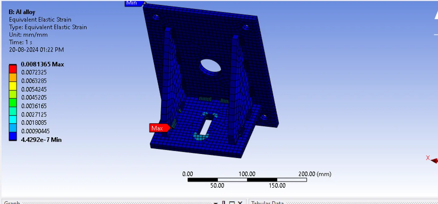
The equivalent stress, directional deformation and equivalent strain are shown below,
CASE 3
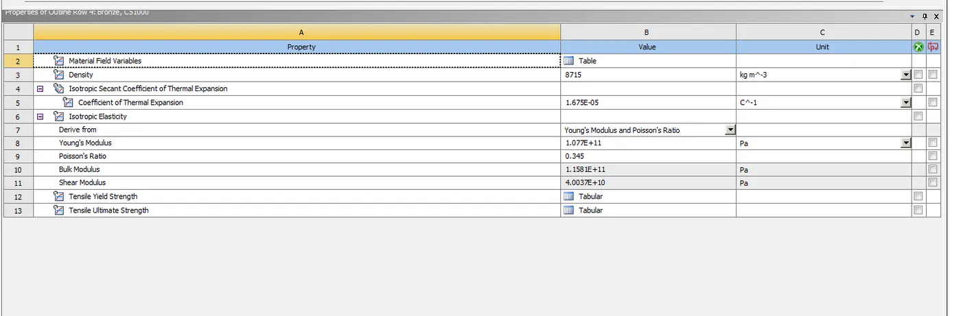
The material used in weld joints are bronze, the properties of the material is shown below,
The material used in plates are stainless steel.
The material used in ribs are copper and the properties are below,
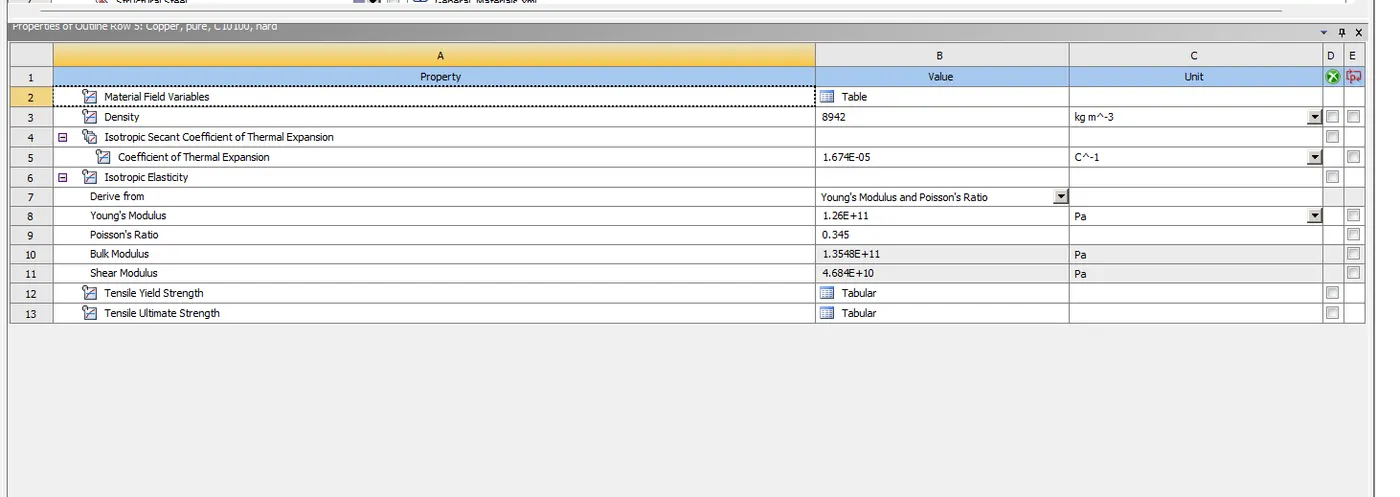
All other procedures are same as case 1.
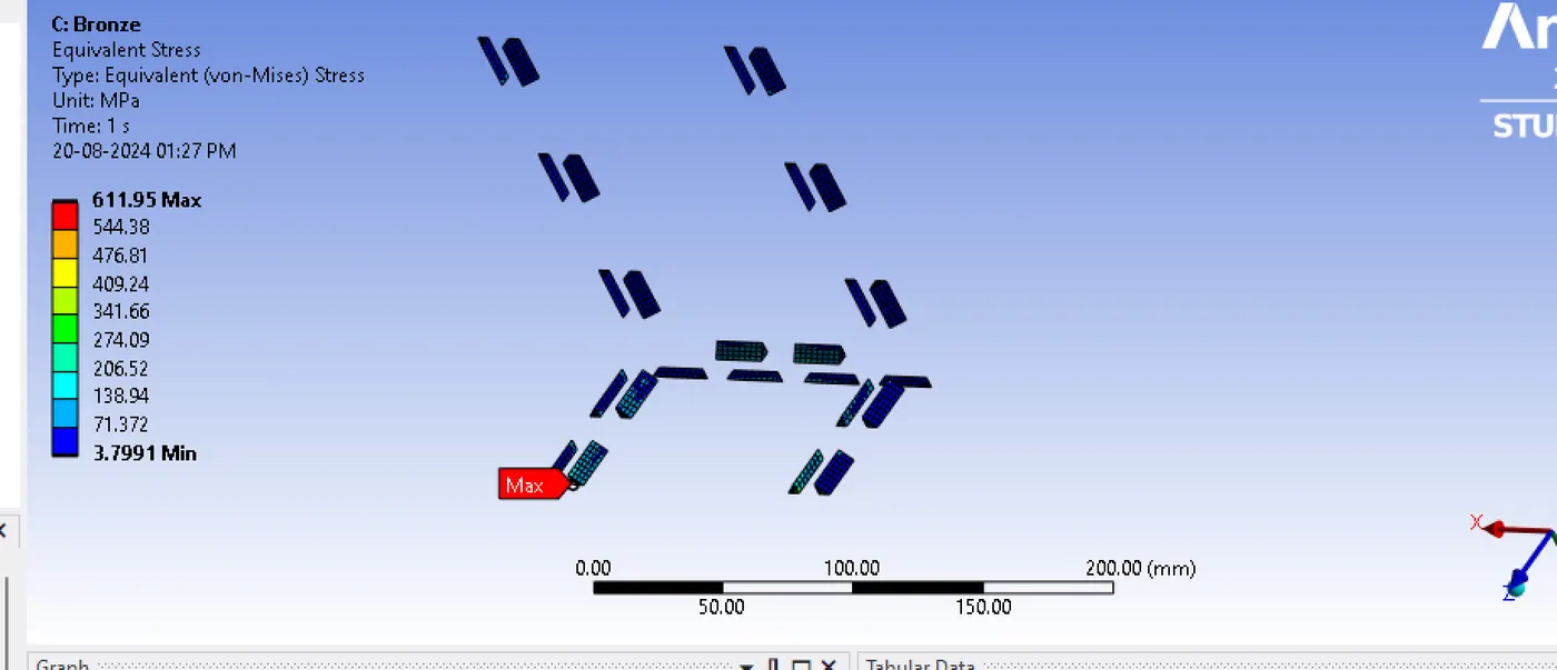
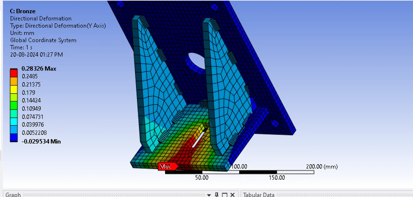
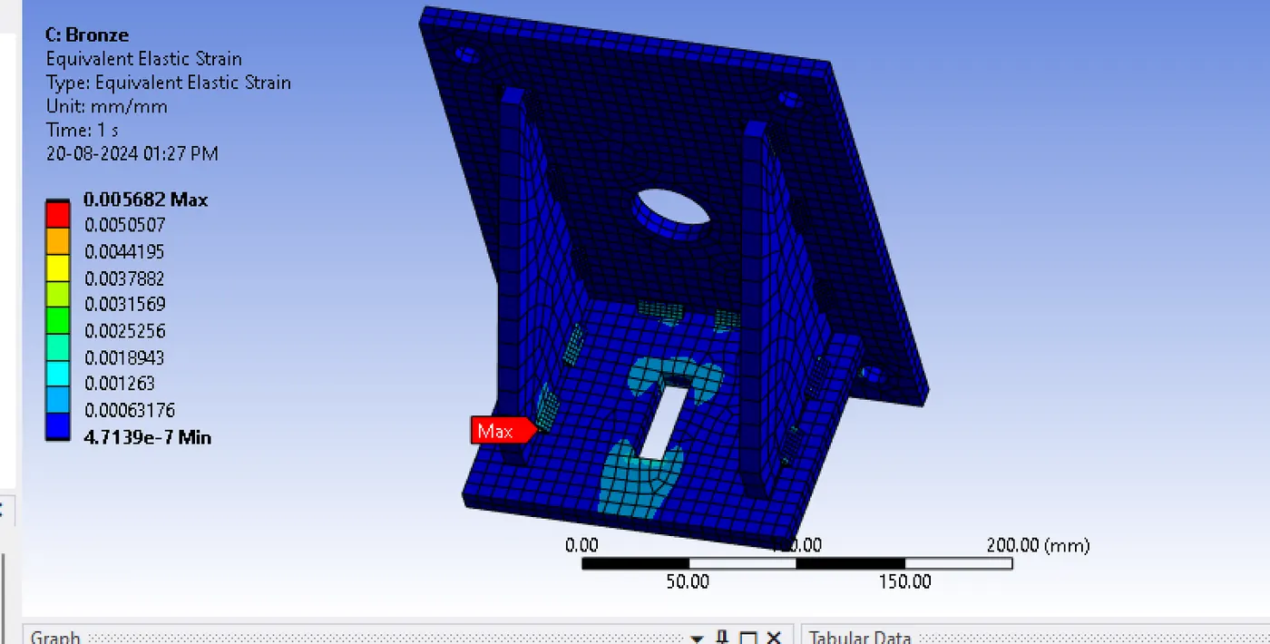
The results of the simulations are listed below,
The results are compared below,
The maximum equivalent stress
case 1 786.26 MPa
case 2 577.69 MPa
case 3 611.95 MPa
The maximum directional deformation
case 1 0.24497 mm
case 2 0.26556 mm
case 3 0.28326 mm
The maximum elastic strain
case 1 0.0040739
case 2 0.0081365
case 3 0.005682
CONCLUSION
The maximum stress developed in case 1 and minimum is developed in case 2. The maximum deformation is developed in case 3 and maximum strain is developed in case 2.
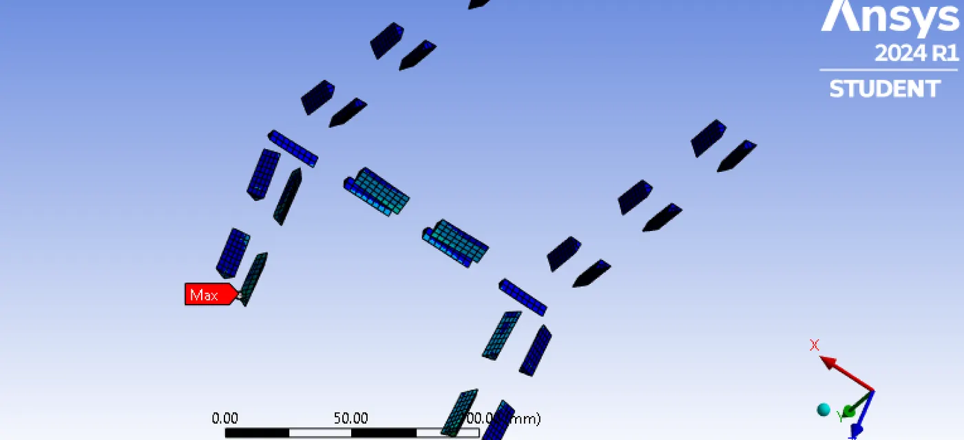
The maximum stress developed in each case is in the same weld joint and its location is shown below. This is because this joint is near the load it is the outermost joint.
Using aluminium alloy as weld material is the best choice.