Week 3 Verification of Weld Joints
Aim : To verify weld joints using static structural analysis
Conclusion :
1) To simulate three different types of welding using three different weld materials
2) To fine out the directional deformation and equivalent strain experienced by the setup
3) To identify the weld joint that experiences…
Introduction :
Welding is a very commonly used permanent joining process. Recent years we have accomplished mngreat advancement in welding technology, it has secured a prominent place in manufacturing machine components. Compared to other type of joints, the welded joint has higher efficiency. An efficiency > 95 % is easily possible. Since the added material is minimum, the joint has lighter weight. Welded joints have smooth appearances. Due to flexibility in the welding procedure, alteration and addition are possible. Forming a joint in difficult locations is possible through welding.
The advantages have made welding suitable for joining components in various machines and structures. Some typically welded machine components are listed below.
1. Pressure vessels, steel structures.
2. Flanges welded to shafts and axles.
3. Crank shafts
4. Heavy hydraulic turbine shafts
5. Large gears, pulleys, flywheels
6 Gear housing
7. Machine frames and bases
8. Housing and mill-stands
Procedure :
1) To verify welds in the setup, we use static structural tool in the analysis system tool box to define the geometry and other input parameters for the same.
First we open spaceclaim to identify and rectify the errors in the geometry. In the below geometry we can see the welds are
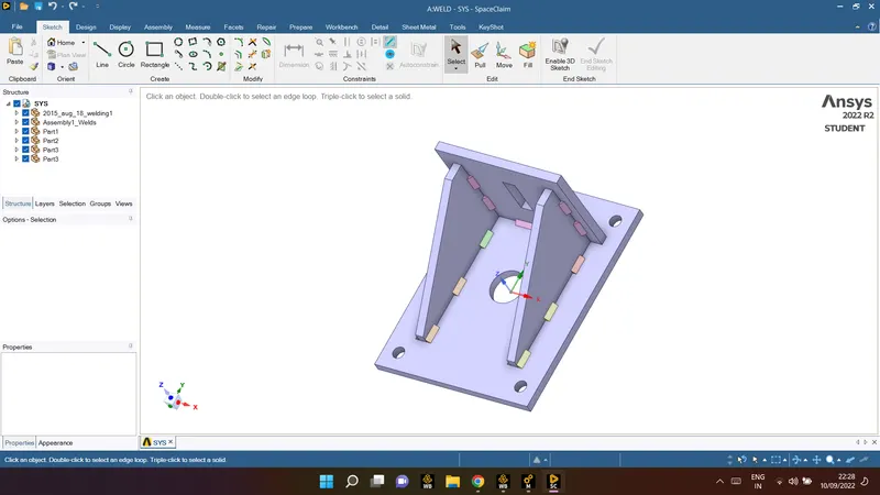
2) In the engineering data we input the material and its properties. In this case we are using three different types of materials and its properties are shown below.
Case 1 :
In this case, the material of the plates must stainless steel. Use Stainless steel for both weldments and plates. No need to add flux to the weldments.
1) assign material for case _1 :
Stainless steel for all the component and weld
2) Connection
| connection | type | coeffiecient |
| big plate to rib 1 | frictional | 0.2 |
| big plate to rib 2 | frictional | 0.2 |
| small plate to rib 1 | frictional | 0.2 |
| small plate to rib 2 | frictional | 0.2 |

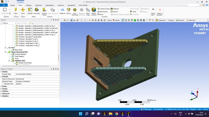
3) Mesh:
body sizing : big plate and small plate = 5mm
generate the mesh
4) Static strctural :
1) fix support
2) force
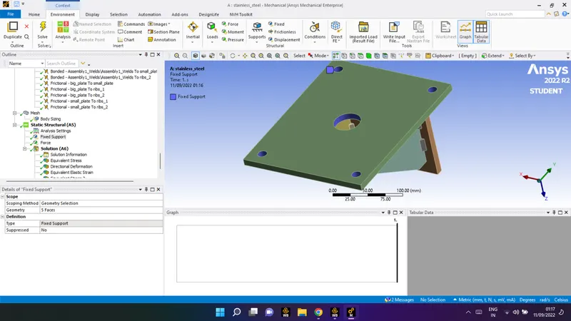
1) fix support :
| scoping method | geometry selection |
| type | fix support |
| geometry | 5 faces |
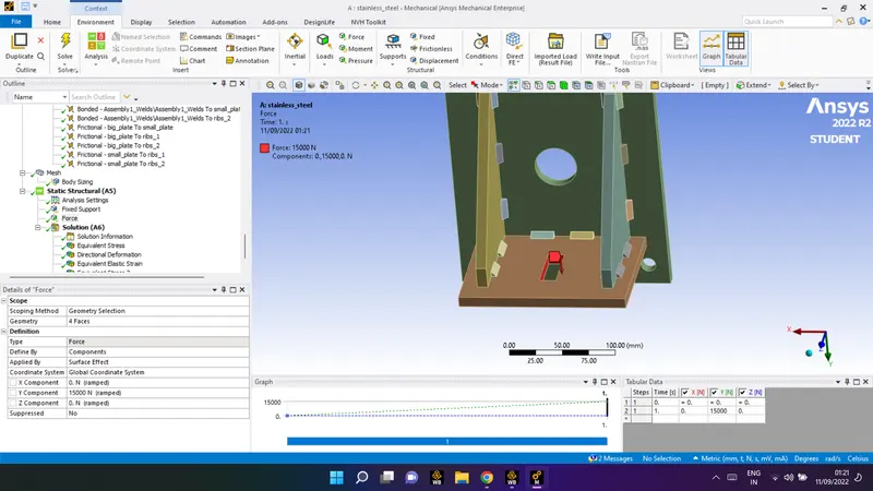
2) force:
| scoping method | geometry selection |
| geometry | 5 faces |
| type | force |
| Defined by | component |
| coordinate system | |
| 1) X component | 0 N |
| 1) Y component | 15000N |
| 1) Z component | 0 N |
Solution parameter we wants:
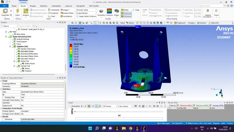
- Equivalent stress
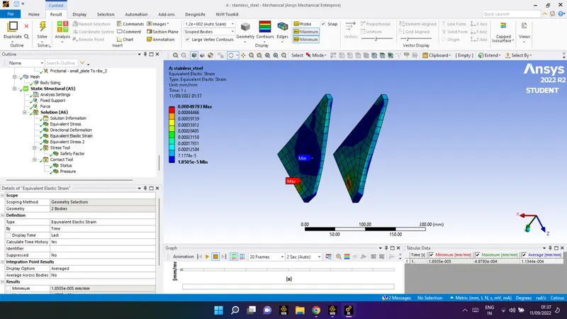
- Equivalent Elastic strain
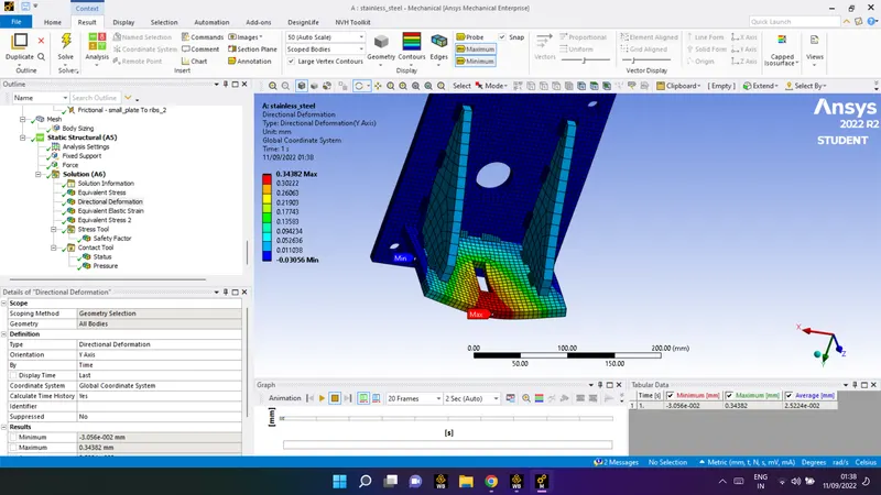
- directional deformation
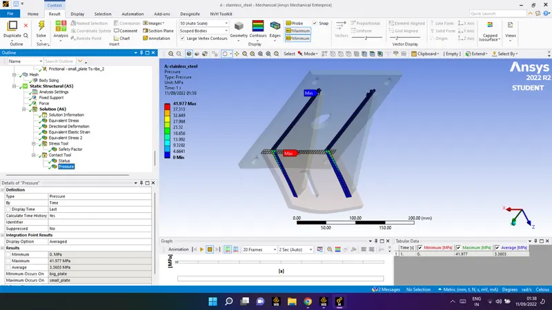
- contact tool (pressure)
- Equivalent stress 2
- stress tool (safty factor)
click on the solve
Result for the solution :
- Equivalent stress
- Equivalent Elastic strain
- directional deformation
- contact tool (pressure)
- Equivalent stress 2
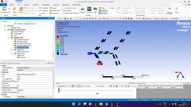
- stress tool (safty factor)
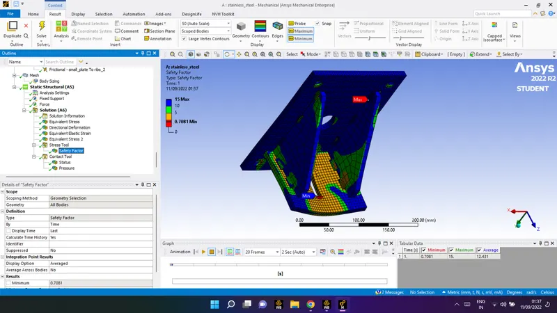
Case 2.
Aluminium Alloy: The material to be chosen for this case is Aluminium alloy(high strength, wrought). [Plate material to be used is stainless steel]
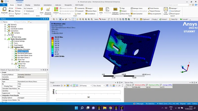
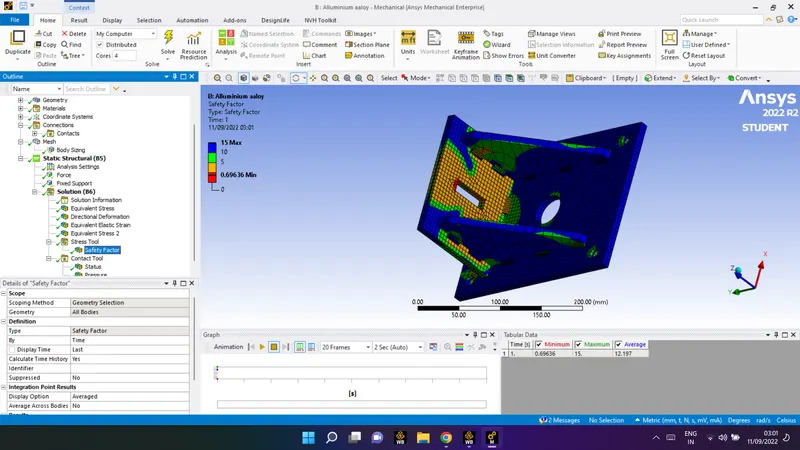
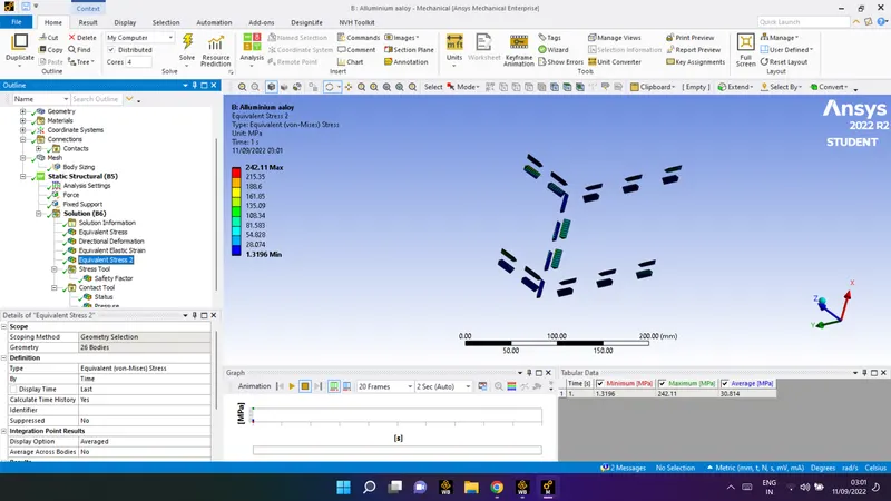
For the case_2 same precedure followed hence the result is shown for the case -2
- Equivalent stress
- Equivalent Elastic strain
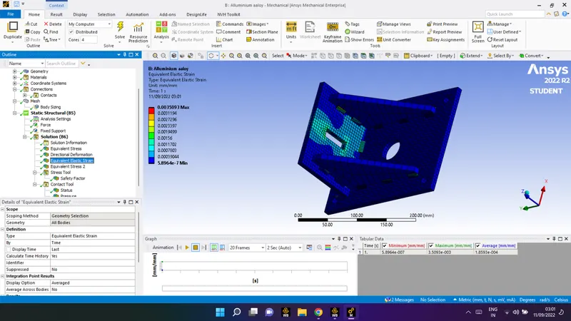
- directional deformation
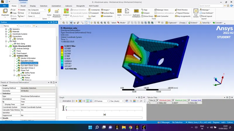
- contact tool (pressure)
- Equivalent stress 2
- stress tool (safty factor)
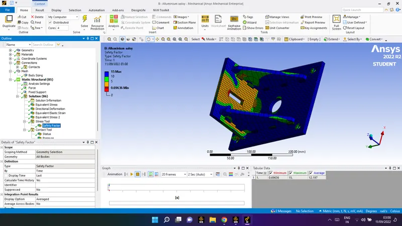
Case 3.
Bronze: In order to simulate "Brazing", you should be using bronze as the weld material. Assign Stainless Steel to both plates and Copper to the "Ribs".
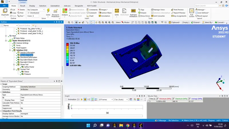
- Equivalent stress
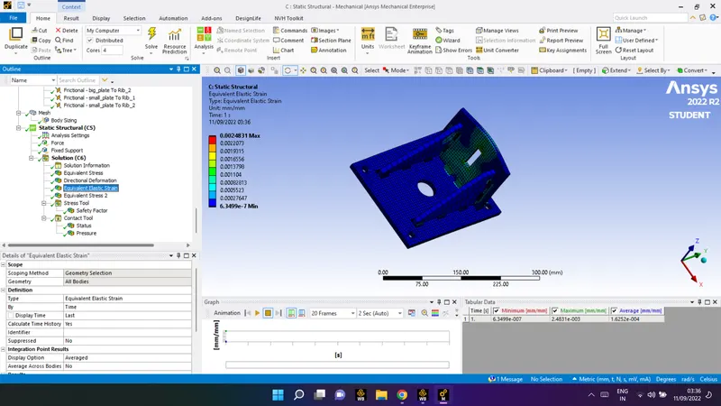
- Equivalent Elastic strain
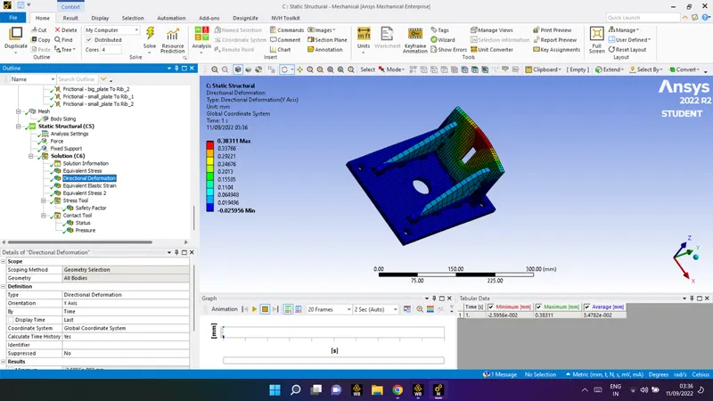
- directional deformation
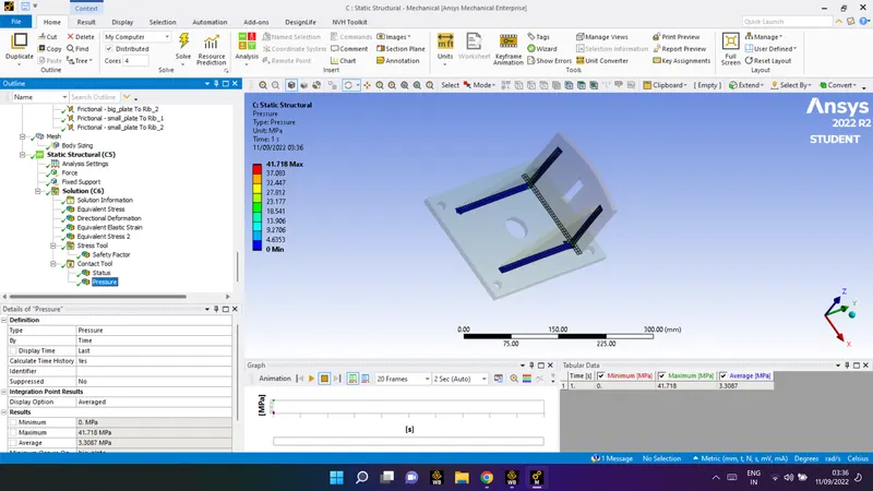
- contact tool (pressure)
- Equivalent stress 2
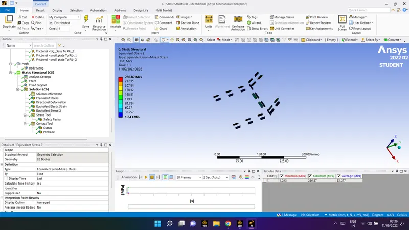
- stress 2 tool (safty factor)
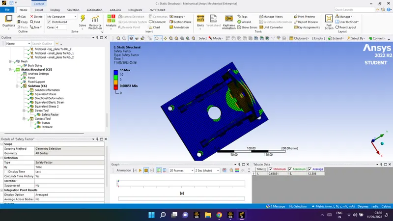
Results :
| Sr. No | Equivalent stress | Equivalent strain | Directional Deformation |
|
Case 1 Stainless Steel |
22.315 | 1.1344e-004 | 2.5224e-002 |
|
Case 2 Alluminium alloy |
24.272 | 1.8593e-004 | 3.2342e-002 |
|
Case 3 Bronze |
25.127 | 1.6252e-004 | 3.4782e-002 |
Conclusion :
We can conclude that from the above results stress on the bronze cast material used for brazing weld joint has the
maximum equivalent stress among the other materials. The directional deformation in the Y axis is also high in case of bronze material.
I have attached the file with this record for the further reference
thank you