Week 3 Verification of Weld Joints
Aim: To simulate a load of 15000N that is to be applied at the rectangular hole in the small plate using three different types of welding using three different weld materials as given below:
Case 1: Use stainless steel for both weldments, plates and ribs.
Case 2: The material to be chosen for this case is Aluminium Alloy (high strength, wrought) and plate material to be used is stainless steel.
Case 3: In order to simulate "Brazing", use bronze as the weld material and assign Stainless Steel to both plates and Copper to the ribs.
For each case, find out the directional deformation and equivalent strain experienced by the setup. Identify the weld joint that experiences the highest equivalent stress in each case and compare the results for all three cases.
Introduction: Welding is a fabrication process whereby two or more parts are fused together by means of heat, pressure or both forming a join as the parts cool. Welding is usually used on metals and thermoplastics but can also be used on wood. The completed welded joint may be referred to as a weldment. Brazing is a process for joining two pieces of metal that involves the application of heat and the addition of a filler metal. This filler metal has a lower melting point than the metals to be joined, is either pre-placed or fed into the joint as the parts are heated. Brazing soundly beats welding when joining dissimilar metals. As long as the filler material is metallurgically compatible with both base metals and melts at a lower temperature, brazing can create strong joints with barely any alteration of the base metals properties.
Procedure:
- After opening Ansys Workbench, use static structural as the mode of analysis for simulation.
- Now, add four materials as given in the objective in the engineering data i.e. stainless steel, copper, aluminium alloy and bronze.
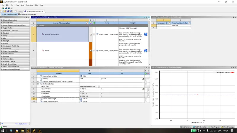
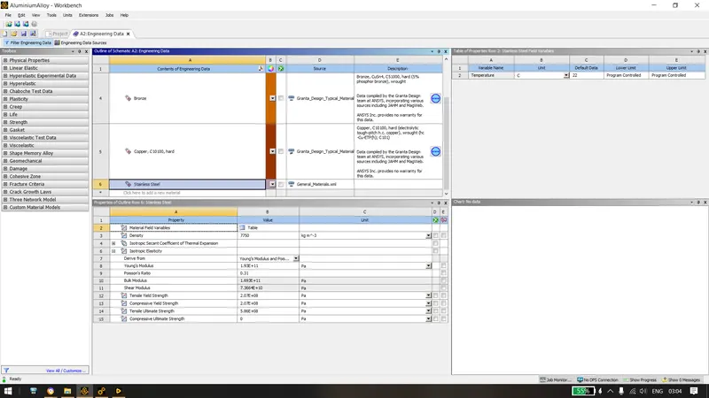
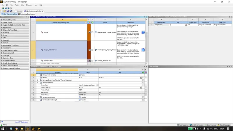
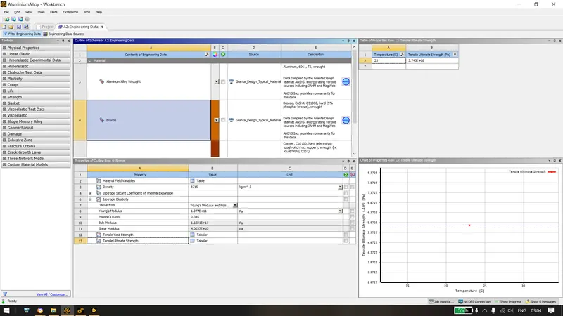
- After adding materials, import the geometry given. Checking the geometry in the Ansys Spaceclaim for any abnormalities.
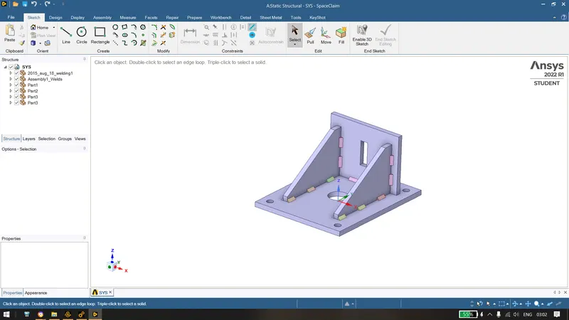
Now for Case1 :
- Apply material as stainless steel to all the parts in the geometry tree as mentioned in the objective.
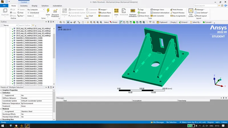
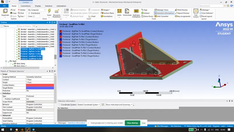
- After applying the material, apply a frictional coefficient of 0.2 between the plates and ribs.
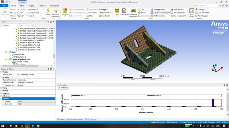
- Mesh the plates and ribs with 6mm and 10mm respectively using face sizing. Then mesh the component.
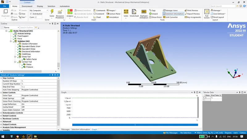
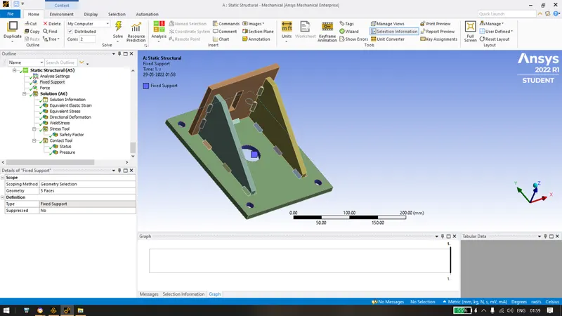
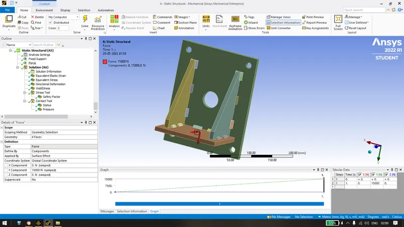
- Now in analysis settings keep no. of steps as 1 and turn on large deflection and also apply a fixed support and apply a force of 15000N to the plate as shown below:
Following Solutions have been obtained after solving for the simulation:
- Maximum strain of 0.0018 has been obtained.
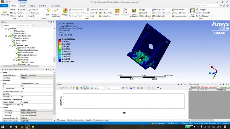
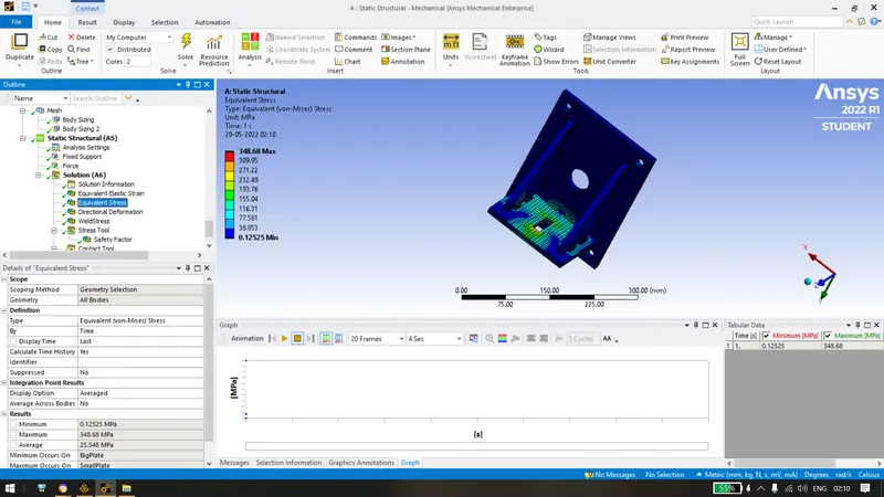
- Max Stress of 348.68 MPa was obtained.
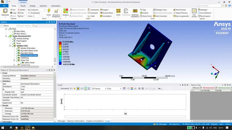
- Directional deformation of 0.351mm was obtained in y axis.
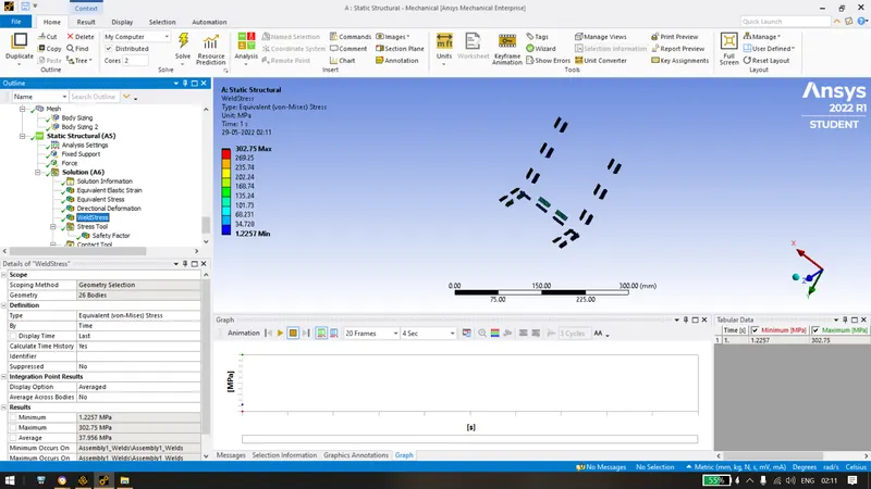
- Max stress of 302.75 Mpa was obtained from all 26 welds on the component.
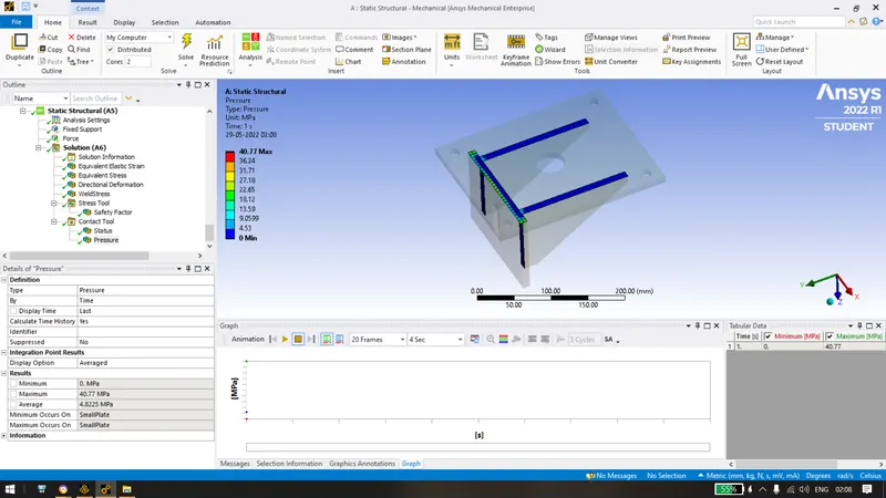
- 40.77 as the maximum Contact Pressure.
- 0.68 was the minimum factor of safety obtained.
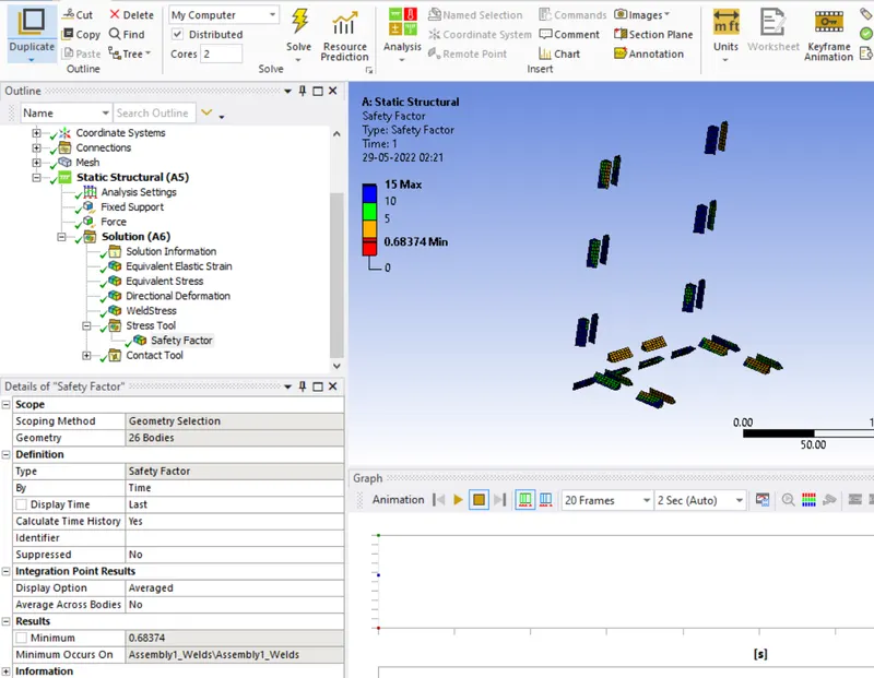
- Similarily, we will be performing the same procedure for the other two cases and the following is obtained:
A) Directional Deformation for case 2 & case 3 respectively.
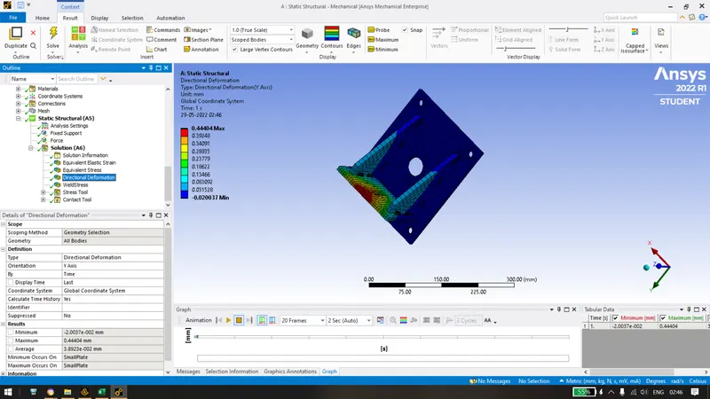
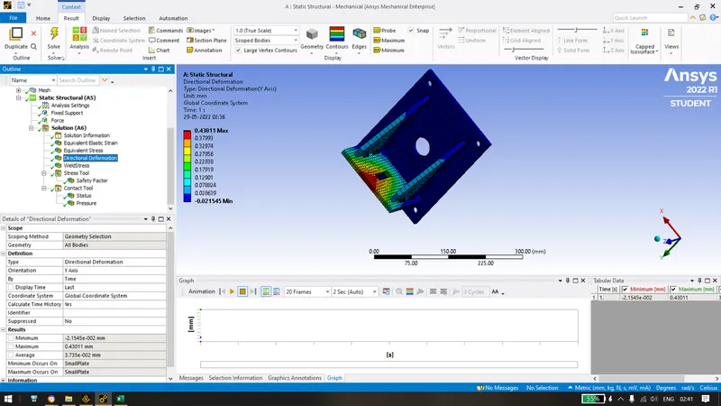
B) Equivalent strain for case 2 & case 3 respectively.
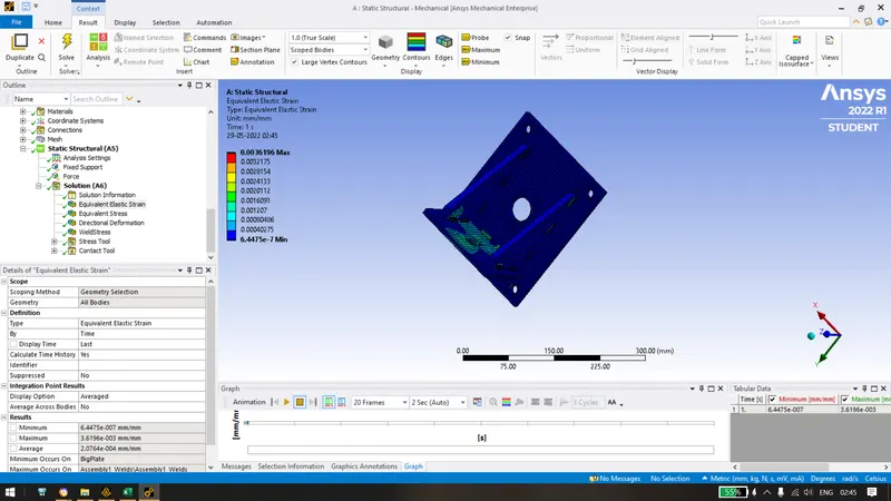
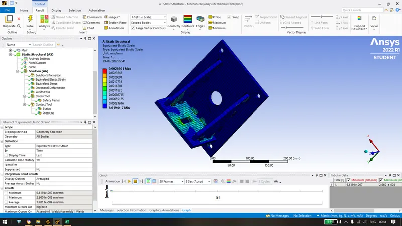
C) Equivalent stress on Welds for case 2 and case 3 respectively.
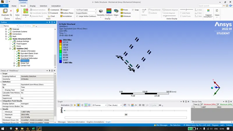
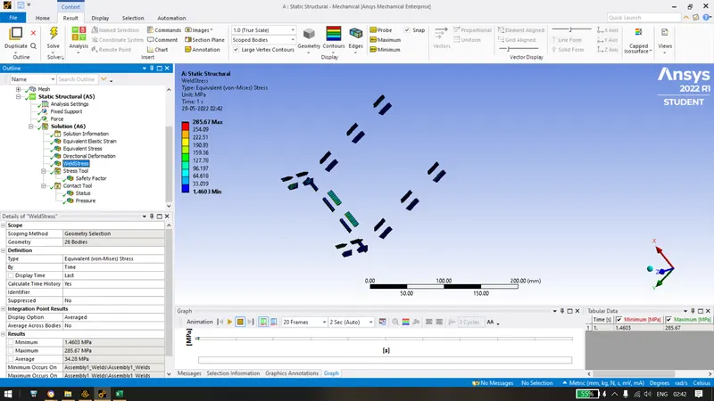
Conclusion:

- From the above results, we can say that the minimum safety factor of 1.76 is highest for case 3 which means that materials used in case 3 are better than the materials used in other cases.
- Also, the difference between case 2 & 3 for directional deformation, equivalent stress and weld stress are very less. Max Weld Stress for case 2 is lower than case 1. Since safety is a major concern, Case 3 materials are suitable.