Week 3 Sheet metal Bending challenge
AIM :
To Performing a Sheet metal Bending by using Four different materials and different frictional values by using ANSYS.
OBJECTIVES :
Case 1:Aluminium Alloy 1199, Copper Alloy NL, and Magnesium Alloy NL. Find out the Equivalent stress, Equivalent elastic strain, and Total Deformation in the Y direction and compare the results for the three materials.
Case 2:With the material as Aluminium Alloy, change the friction coefficient to 0.19 and run the analysis as mentioned in Case 1. Compare the results with that in case 1.
Case 3: Refine the mesh on the plate such that it doesn't cross the academic limit. With Aluminium alloy as material, run the analysis as in Case 1 and compare the results.
INTRODUCTION :
A Sheet metal bending is one of the manufacturing processes, mostly ductile material is used because it easily allows us to change the shape of the component like V shape, U shape, or any other channel shapes without any fracture.
A Setup is consists of Die, Punch, Workpiece, and workpiece guide. Usually, Die & Punch materials are stronger than the Workpiece, a workpiece material should be always lesser strong than a die material.
PROCEDURE
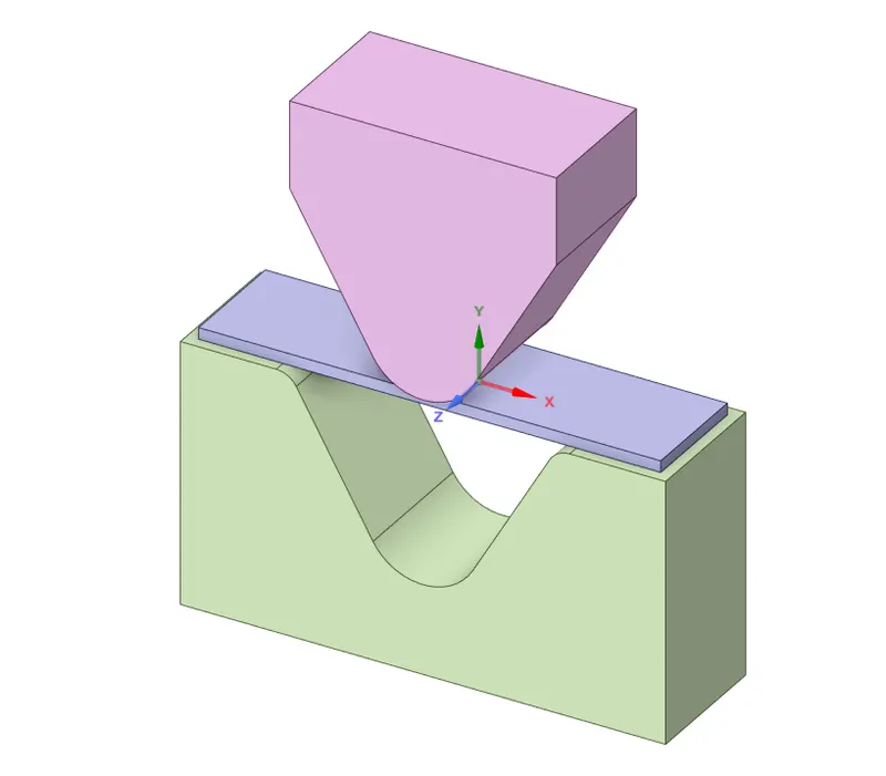
- A Sheet Bending components are given from the Design team. We have to import the model into the Geometry section, in order to verify the model before going to any process. Open a Space Claim or Design Modeller to verify or edit the geometry based on our requirements. In this case, a given model has been perfect, it looks like as shown in the below image.
Materials Details :
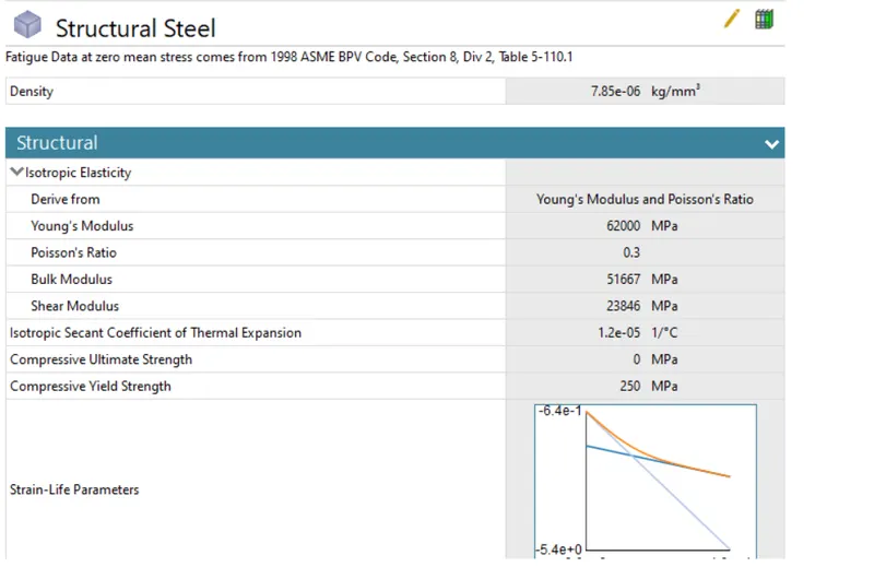
- We should use four different materials for Sheet metal as a workpiece and use Structural Steel material for Die & Punch.
Structural Steel :
Aluminium Alloy 1199 :
Aluminium Alloy :
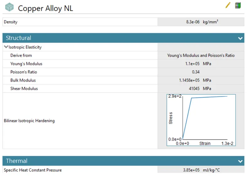
Copper Alloy Non-Linear:
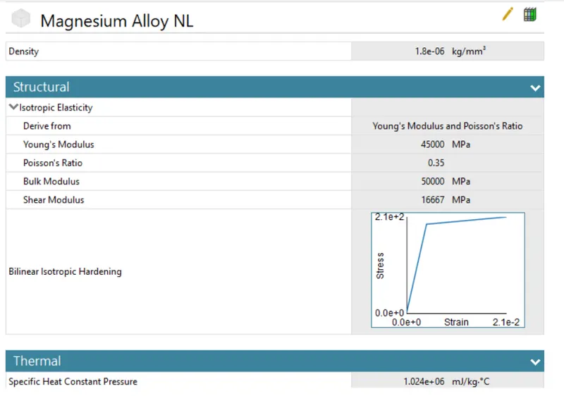
Magnesium Alloy Non-Linear:
Assigning a Material :
- Assigning a structural steel material for die & punch in all cases.
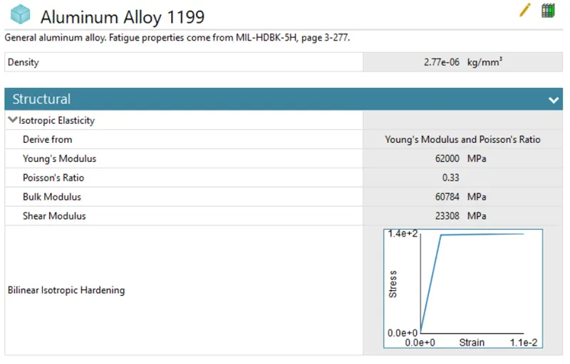
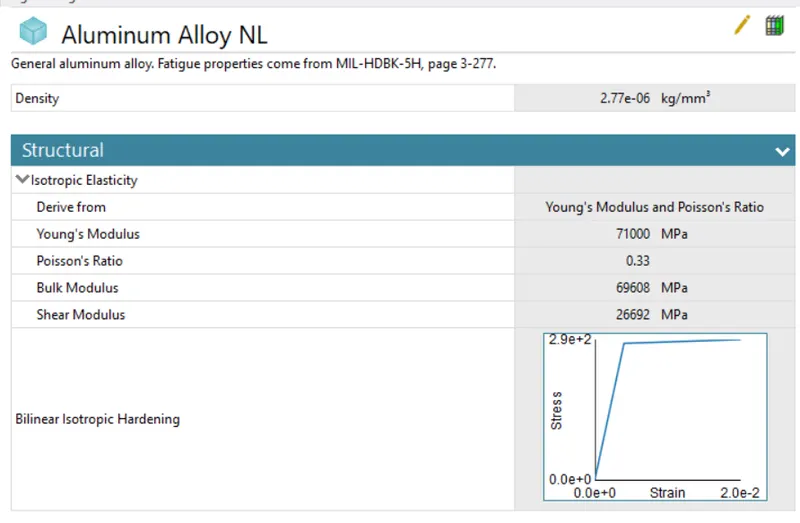
- We should assign the materials for the Work piece like Non Linear Copper Alloy & Magnesium Alloy, Alluminium Alloy and Aluminium Alloy 1199 according to request.
Connections :
- We have to Create two contacts between the components. One is made between Punch and Sheet and another one is made between Punch & sheet.
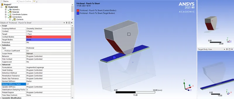
Punch to Sheet :
- Select the punch cone face as a Contact Bodies and Select the Workpiece top face as a Target Bodies.
- Select the Contact type that is Frictional with a 0.1 Coefficient of friction between the contacts.
- Keep "Auto Asymmetric" as a Behavior.
- Keep Formulation as "Augmented Lagrange" Algorithms which help to increase the stiffness of the contact and resists the penetration between them. This type of algorithms has used any type of contact.
- Keep Add Offset, No Ramping for Interface treatment.
- Keep remaining options are as it is.
Sheet To Die :
- Select the bottom face of the workpiece as a Contact body and Select the surface where the bottom of the workpiece has been contacting as a Target Bodies.
- The remaining things are as same as what we put in the first contact.
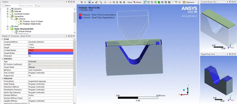
- We can use 0.1 as a frictional coefficient for Aluminium Alloy 1199, Copper Alloy, Magnesium Alloy as workpiece material. Once we have done this, we gonna 0.19 as a frictional coefficient for Aluminium Alloy as a Workpiece material.
Meshing :
- Basically, To divide the entire model into infinitesimal control volume, that framework is called Meshing. This process is called Discretization. This FEM is widely used for solving partial differential equation in different physical field such as Structural problem, Heat transfer problem, Fluid flow problem, Electromagnetic Analysis & Acoustics Analysis.
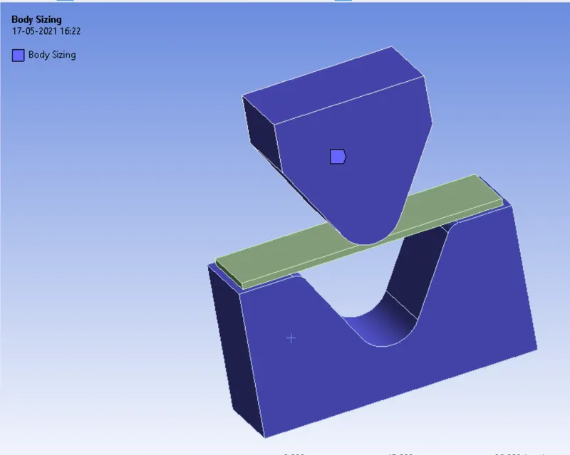
Body Sizing on Punch & Die :
- Select the Punch & Die bodies and meshing with mixed type of element, the size of the element is 4 mm.
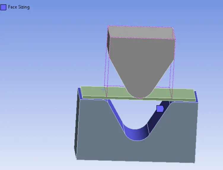
Face Sizing on Contact face :
- Select the face of the contact surface and meshing with the size of the element is 1 mm.
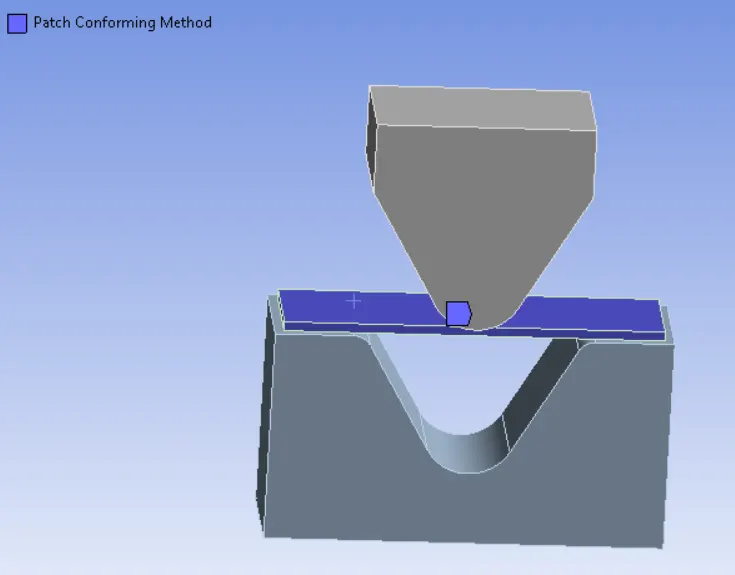
Body Sizing on Workpiece :
- In this workpiece, we have meshed with only tetrahedral elements. In order to mesh with tetra elements, we have chosen the respective algorithm which is Patch Conforming Method.
- And also refine mesh with an element size of 1 mm.
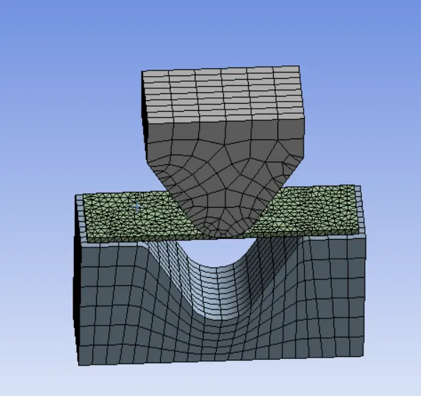
Final Discretized Model :
- Number of Nodes = 17850
- The number of Elements = 6224
- Punch has meshed with mixed type of volumetric elements.
- Die meshes with Hexahedrons Volumetric elements.
- A Workpiece meshes with Tetrahedrons Volumetric elements.
- After done the meshing on the model, it looks like as shown in the below image.
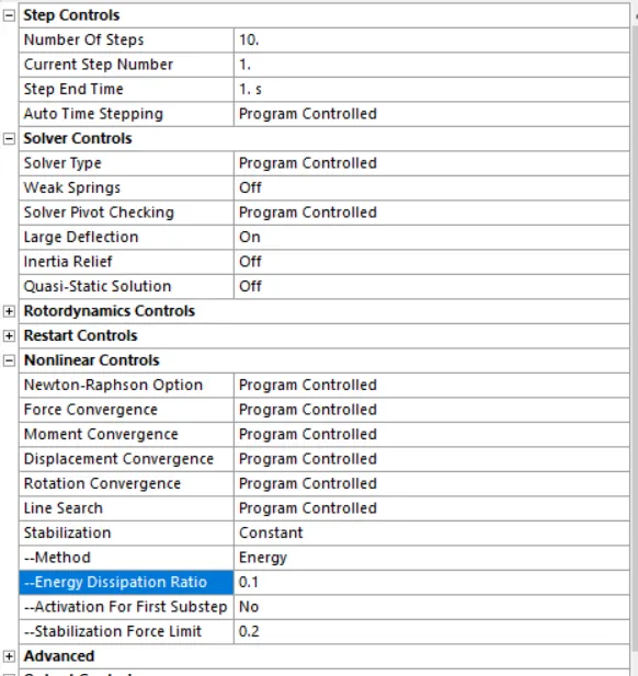
Analysis Settings :
- The number of Steps is 10
- Keep "Program Controlled " for Auto Time Stepping.
- Keep "Direct" for Solver Type.
- Change into "Constant" for Stabilization and Provide the 0.1 as the value of Energy Dissipation Ratio. Keep the remaining options are as it is
Boundary Conditions :
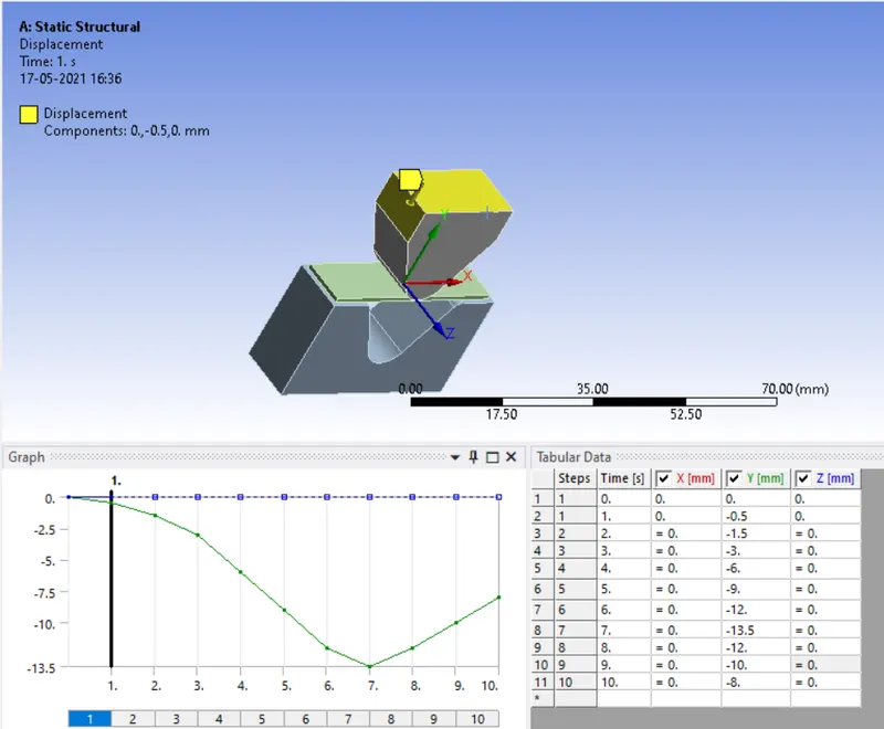
Displacement Joint 1 :
- In order to bend the sheet metal, a punch has been a move in the negative Y direction. Select the top face of the Punch, provide the displacement range from 0 to -13.5 mm with an interval of random values or divide based on a number of steps and keep as free for the X & Z axis.
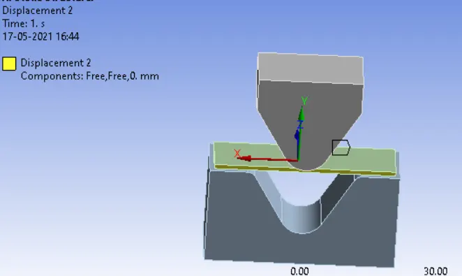
Displacement Joint 2 :
- Constraint the displacement of the workpiece along the Z direction.
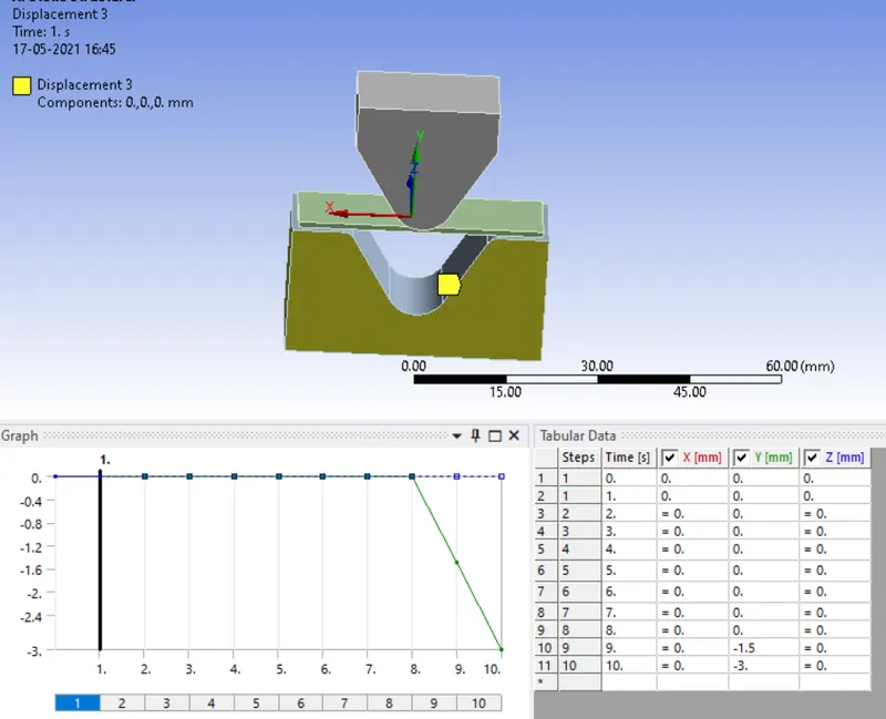
 Displacement Joint 3 :
- Constraint the displacement of the Die on along all directions.
RESULTS :
CASE 1:
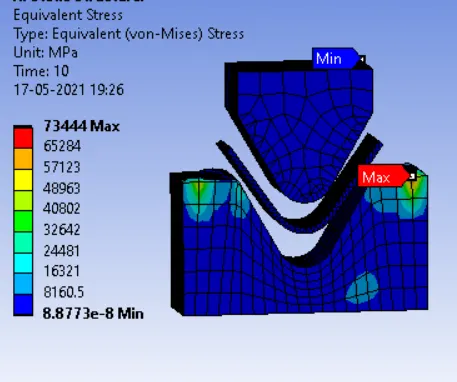
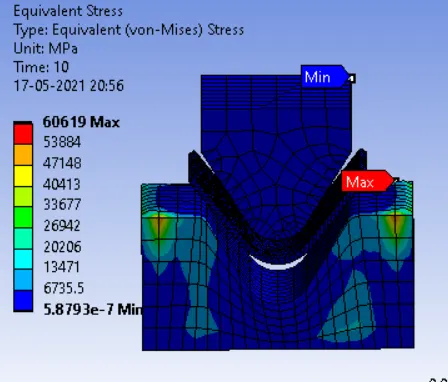
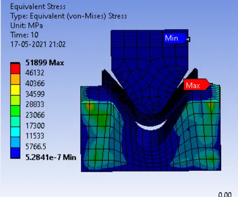
Equivalent Stress :
- A Maximum Equivalent Stress developed on the centre area of the workpiece due to less cross-section area and yield stress of the workpiece is less than the rest of the components like punch & Die.
- While bending the workpiece, tensile stress is developed on the bottom of the workpiece. Same as compressive stress is developed on top of the workpiece.
Aluminium Alloy 1199: Copper Alloy Non-Linear: Magnesium Alloy Non-Linear:
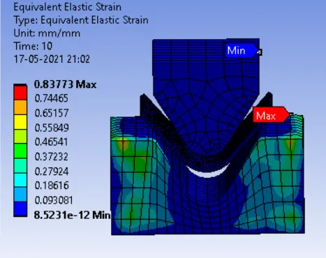
Equivalent Elastic Strain :
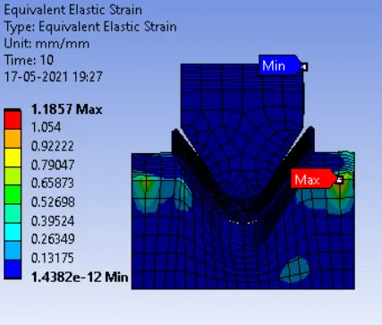
- A Maximum Stress is developed beyond the Elastic Stress of the workpiece, So it leads to a change of the shape permanently even we removed the applied load on it.
- Each workpiece material has different mechanical properties, due to that Elastic strain has been varying.
Aluminium Alloy 1199: Copper Alloy Non-Linear: Magnesium Alloy Non-Linear:
Directional Deformation on Y direction :
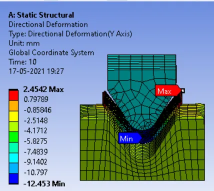
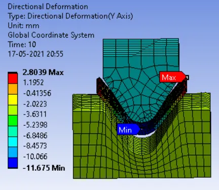
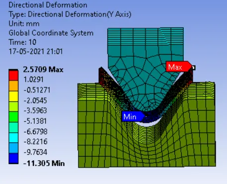
- We provided the displacement distance for a punch up to 13.5 mm in the negative Y direction, based on that simulation has run through.
- Directional Deformation in the Y direction is around 13 mm - 13.5 mm for all cases.
Aluminium Alloy 1199: Copper Alloy Non-Linear: Magnesium Alloy Non-Linear:
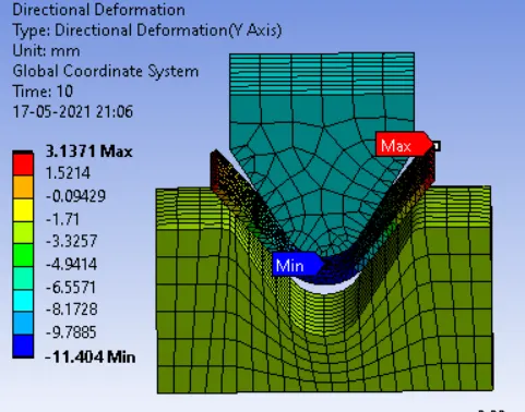
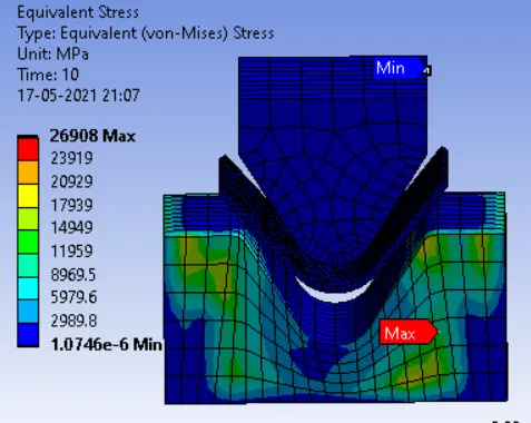
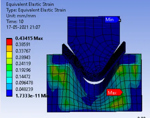
Case 2:With the material as Aluminium Alloy, change the friction coefficient to 0.19
Directional Deformation: Equivalent Stress : Equivalent Elastic Strain
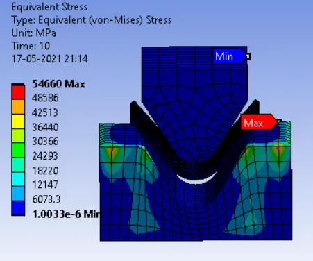
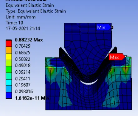
Case 3: Refine the mesh on the plate With Aluminium alloy as material
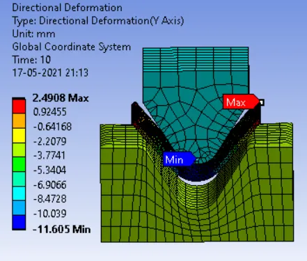
- we have to refine mesh element size by 0.8mm.
Directional Deformation: Equivalent Stress : Equivalent Elastic Strain
CONCLUSION :
Case 1:
- Equivalent Elastic strain & Deformation are pretty same for case 1 material. But, Equivalent stress has been varied drastically as compared to Aluminium Alloy 1199 than Copper & Magnesium Alloy material.
- An Aluminium Alloy 1199 has consumed less power for getting the required shape than compared to the remaining two materials. But the Strain is vice versa to stress.
- So, We choose Magnesium Alloy as workpiece material, because it's got decent Equivalent Elastic Strain and Directional Deformation also be almost the same as what we put in the displacement value.
| Work Piece Materials | Equivalent Stress(max) in Mpa | Equivalent Elastic Strain(max) | Total Deformation(max) On Y Direction in mm |
| Aluminium Alloy 1199 | 73444 | 1.1857 | 2.4542 |
| Copper Alloy Non-Linear | 60619 | 0.97856 | 2.8039 |
| Magnesium Alloy Non-Linear | 51866 | 0.83773 | 2.5709 |
Case 2 & 3 :
- A Stress development is very high as compared to case 1 materials. And also Elastic Strain value is increased more as compared to the case 1 material.
- When we refined the workpiece, we got a more accurate solution. But, the computational time & Storage required for saving data is obviously too high.
| Work Piece Material | Equivalent Stress in Mpa | Equivalent Elastic Strain | Total Deformation On Y direction in mm |
| Aluminium Alloy | 26908 |
0.43415 |
3.1371 |
| Aluminium Alloy with Refinement | 54660 | 0.88232 | 2.4908 |
CONCLUSION
- Magnesium alloy is having low deformation as compared to copper alloy and aluminium alloy, So that means the life of the product made with this material will be more than others and also magnesium is a lightweight material. So it can be used in applications where we need to have low weight but need high strength. Also, we came to know that the refined mesh will be providing more accurate results than the other one with more coarse mesh, at the cost of some computational time