Week - 4 - 2D meshing for Plastic components
ABSTRACT:
- By using CAE Pre-Processing Tool ANSA & to develop 2D meshing for a Bottle Gap
- The Bottle Cap which comes with a plastic material usually have different varying thickness across and threads inside it make it much complex for pre-processing
METHODOLOGY:
- Importing the CAD geometry of Bottle Cap in ANSA
- Checking out the errors and Assigning Property ID (PID)
- Extracting Mid-Surface (3D to 2D interpretation)
- Joining & Extending the individual Surfaces that are included in Mid-Surface
- Assigning Quality Criteria
- Meshing and Improving Mesh Quality.
INTRODUCTION:
Keeping safety, strength, and many design aspects, Bottle Cap has to undergo many conditions, and the final CAD outcome is considered for pre-processing in ANSA.
PROCEDURE:
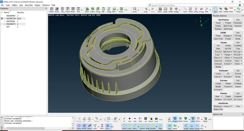
- Importing CAD Geometry of Bottle Cap in ANSA:
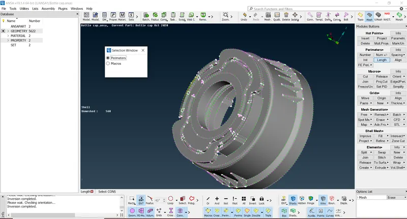
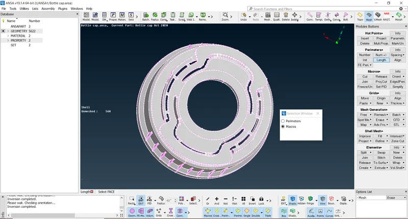
- After successfully importing the Bottle Cap CAD geometry we need to give the Target Length/ Average Length which is assigned as 1 under Mesh Mode
- Checking Out for Errors and Assigning Property ID (PID):
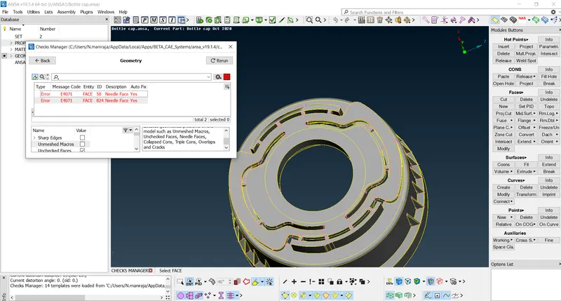
- We need to perform the geometry check under CHECKS Manager in order to see any geometrical problems of the model such as Unmeshed Macros, Unchecked Faces, Needle Faces, Collapsed Cons, Triple Cons, Overlaps, and Cracks.
- ANSA detects some errors and we need to ensure that these need to fixed manually or by just running the automatic fix command and confirm that there are no geometry errors there in the model.
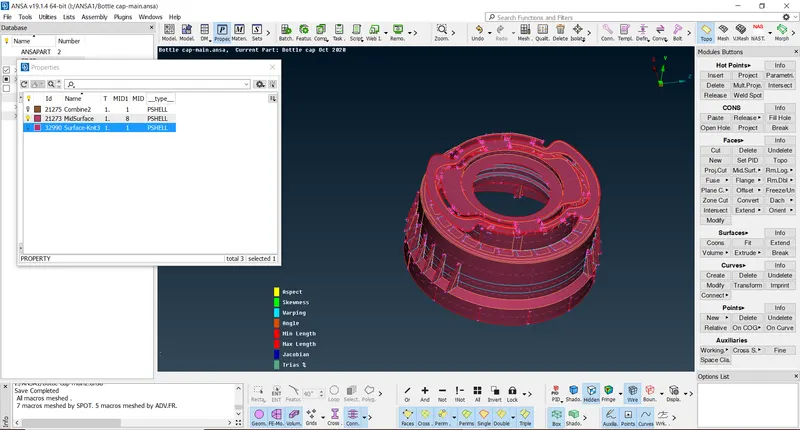
- For any component, we need to assign Property ID(PID) for each and every part so as to differentiate individual checks in our process in later stages.
- This helps in switching to different parts specified upon user requirements.
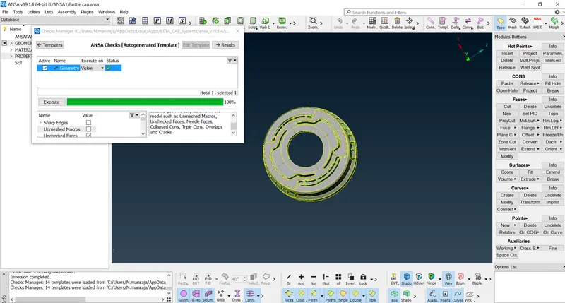
- Make sure that the Bottle Cap is always Gray which indicates Positive in ANSA where yellow stands as Negative.
- Use the Orient option under Faces in Topo Mode to change the color of the model to Gray if it’s so. (Orient
- Extracting Mid-Surface:
- In order to Mesh the component, it needs to undergo mid-surfacing for all the surfaces involved as the component becomes a 2D object after extracting Mid-Surface and it will be ideally good for Meshing.
- There are different methods a CAE engineer can use for Mid-Surfacing the component and the best would be Mid-SurfaceModules Buttons in Topo Mode.
- Here I used Offset Mid-surfacing as it's easy and much efficient for complex surfaces.
- Always enable Cross Hatch while extracting Mid-surface as it helps to select a particular region and space so as to avoid unnecessary errors.
- Create a separate PID for all the Mid-Surfaces Extracted in the Property ID Manager in order to obtain the results at the end.
- By using COG under Points thereby created 26 teeth across the inner surface of the model in just a click.
- Excess parts are avoided and need to be deleted.
- Switching on the transparency mode of Parent Geometry enables whether the surface is aligned properly or not.
- Delete the excess Hot-Points that may affect the Mesh flow in later stages.
- By using Intersect & Extend the Ribs are stitched to the base Mid-Surface and confirmed by triple cons formed in blue color.
EXTRACTING MID SURFACE FOR THREADS:
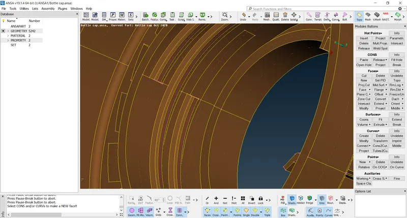
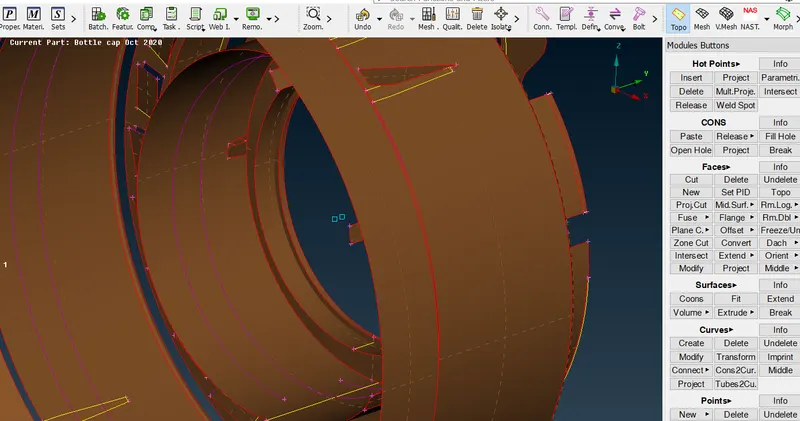
- The middle option under curves is used to create a Curve at the middle of the selected two CONS
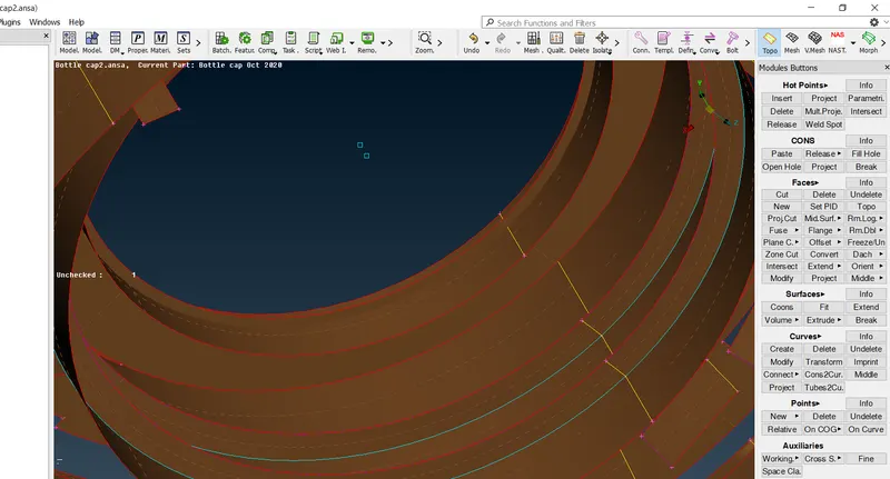
- Fine options in Auxiliaries can be used to click multiple times over Purple colored curves to increase the resolution of the curve. By doing this, a curve will come on the top surface of the thread.
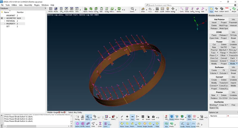
- The Middle Curve is then projected in a Normal direction to the base Mid surface.
- After Projecting the Middle curve to the side Mid surface, It will look like the image shown below
- Pick Double CONS and the Middle curve and create a new surface, which will be the mid surface of the Thread
- Assigning Quality Criteria:
- The average length alters the shell element length of the component.
- The remaining values are assigned in the Quality Manager or just tapping the F11 key.
- Each element in the Mesh should qualify the Quality Criteria given.
- After assigning the values given for the quality check, we need to perform the topological clean-up before meshing.
|
S.No |
Quality Criteria |
Value |
|
1 |
Target/Average length |
1 |
|
2 |
Minimum Length |
0.5 |
|
3 |
Maximum Length |
3 |
|
4 |
Aspect |
3 |
|
5 |
Warpage |
15 |
|
6 |
Skewness |
45 |
|
7 |
Jacobian |
0.7 |
|
8 |
Minimum Quad Angle |
45 |
|
9 |
Maximum Quad Angle |
135 |
|
10 |
Minimum Tria Angle |
30 |
|
11 |
Maximum Tria Angle |
120 |
|
10 |
Tria Percentage |
15 |
Topological Clean-Up:
- So as to acquire the smooth flow of mesh a CAE engineer should do topological clean-up for each and every corner of the model and examine, remove unwanted CONS by using different options available under Module Buttons, mostly used keys are cut, release, insert & delete.
- Meshing and Improving Mesh Quality.
Meshing:
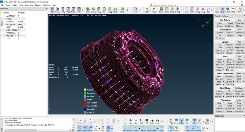
- After Topological Clean up, consider meshing each and every part separately
- One can use different methods in order the Mesh the surfaces, I used the Best Meshing option under Mesh Generation in Mesh Modules Buttons.
- Best Mesh ensure the user a good Mesh flow across the part and ANSA provides a decent outcome.
- Once the Meshing is done, try to reconstruct the Mesh generated and Smooth it for enhancing the Mesh.
Improving Mesh Quality:
- Once the Meshing is done with the desired quality criteria, we need to ensure there should be no unnecessary rotating Trias or Quad elements in the model.
- No Tria elements on the edges
- And OFF elements should be zero in order to achieve quality.
- Trias and Quad elements can be adjusted using the Split & Swap options under Element Option, smooth the elements again and again till the flow is fine and accurate.
- In some cases, use the Paste option under the Grids bar to clean the Tria and Quad elements from the Edges.
RESULT:
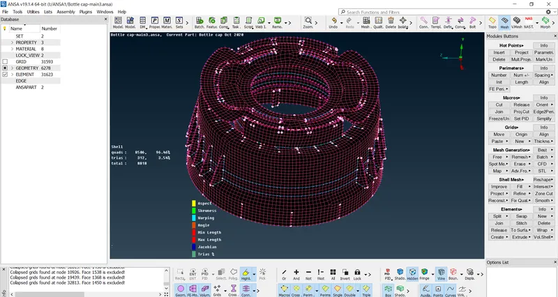
- A 3D Bottle Cap is Meshed successfully converting into the 2D surface by extracting its Mid-Surface giving the quality criteria and performed the Meshing, Improving Mesh Quality using different tools with the help of ANSA.
- As ANSA is a trial and error tool user should follow the steps again and again in order to get the desired output.
- Finally, the Bottle Cap is saved as Draw Shell as Solid obeying the thickness criteria.
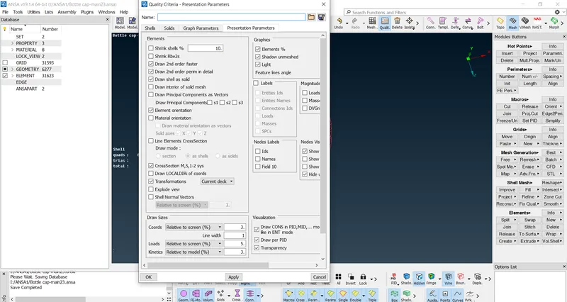
FINAL BOTTLE CAP MODEL:
Learning Outcome:
- Able to analyze the model, extracting the MID surface for different parts involved.
- Checking the Geometry and creating Mid-Surface for each part (3D to 2D extraction).
- To assign Quality criteria.
- Generating Mesh & checking the quality of Mesh.
Google Drive link: https://drive.google.com/file/d/1n6wDeHitbGOn5apd2merxdkVWRigsODH/view?usp=sharing