Week 3 Sheet metal Bending challenge
AIM:
To performt the simulation for sheet metal bending.
PROCEDURE:
- First we will import the model file in ANSYS and after we will edit the model in spcaeclaim.
- First start the structural analysis and open the model.
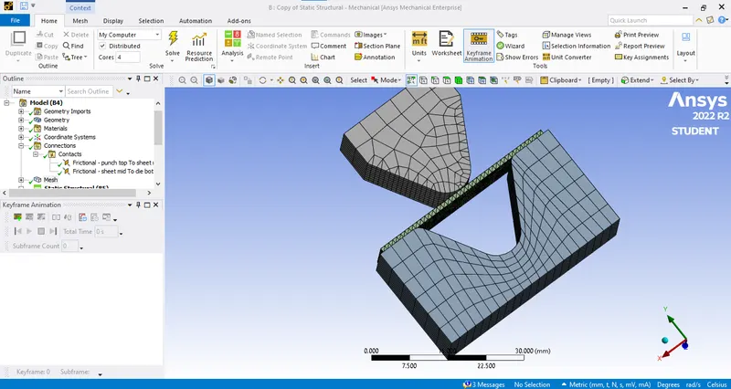
- The model is shown below:
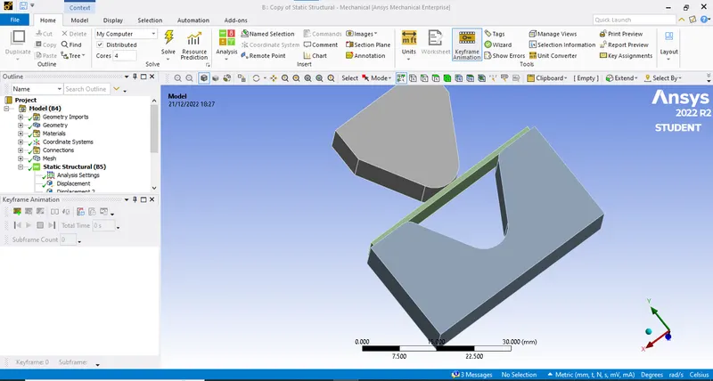
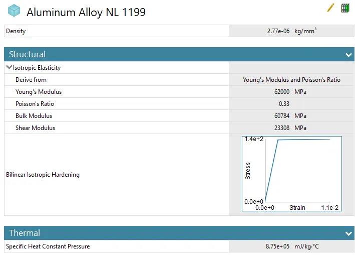
- Now first we will select the material for the sheet. So in this we are using 3 material and comparing the result of each of them.
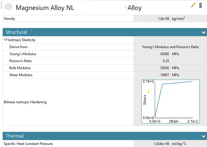
- The materials are Aluminium Alloy 1199,Copper Alloy NL and Magnesium Alloy NL
- After that the connections are applied which are shown below:
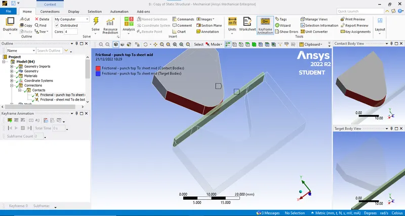
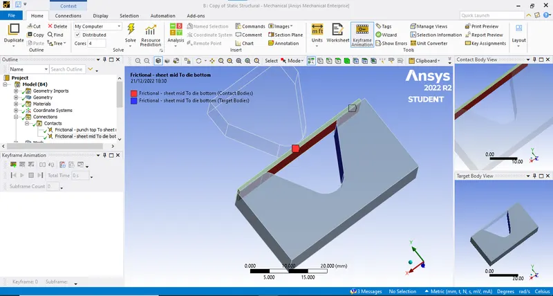
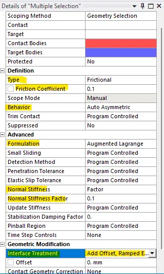
- Now add friction and other factors as showm:
- Now after this we will mesh the component. The mesh size for the die and punch is 4 mm and the mesh size for the sheet and the faces of die and punch is 1 mm.
- And select the tetrahedron mesh for the sheet.
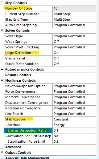
- Now after this we change the analysis setting as shown below:
- And also select solver type as:DIRECT.
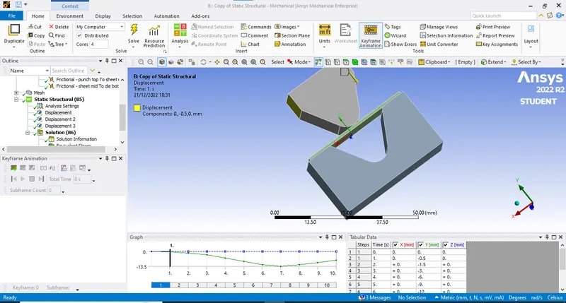
- Now we will apply the load. First is a displacement of a die on sheet as shown below:
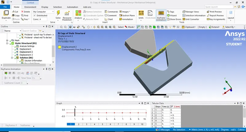
- Now as we punch the die we dont want sheet to expand alond z dierection so we will selec the side of the sheet and restrict them as shown.:
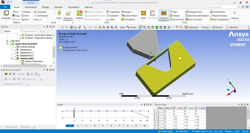
- Now for the punch the required displacement is shown below:
- Now after this we have to assign the output parameter. Which are Equivalent stress, Equivalent elastic strain and Total Deformation in Y direction.
- Now after this we will comapare the results with different material.
CASE 1:
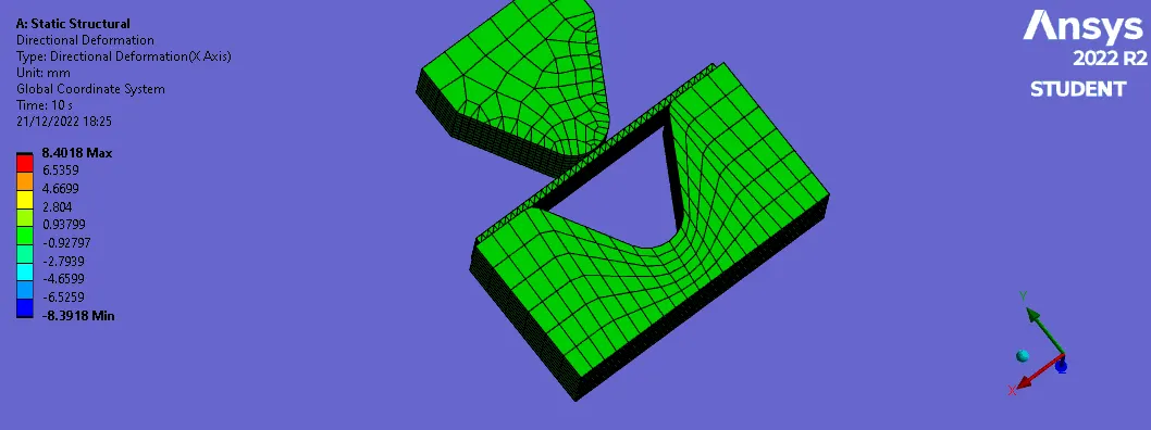
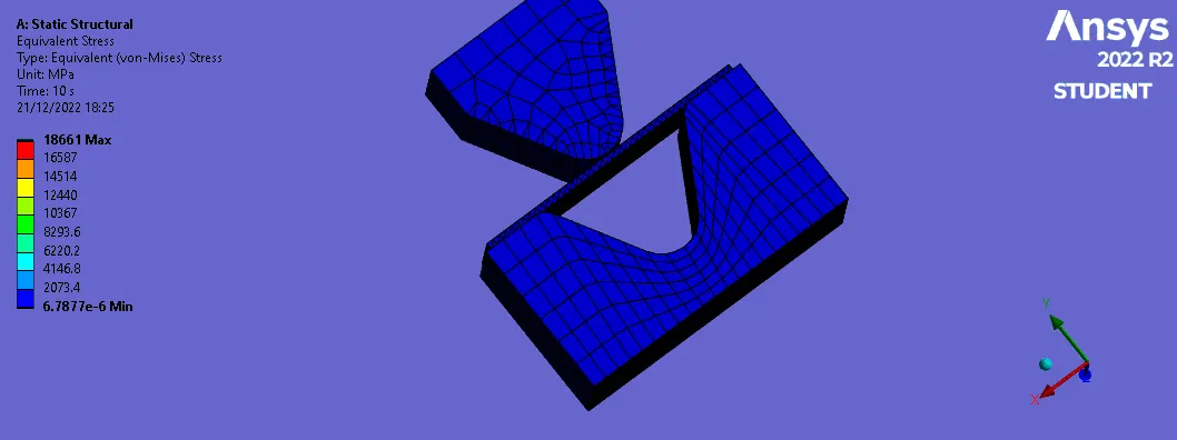
Aluminium Alloy 1199
Directional Deformation
Equivalent Stress
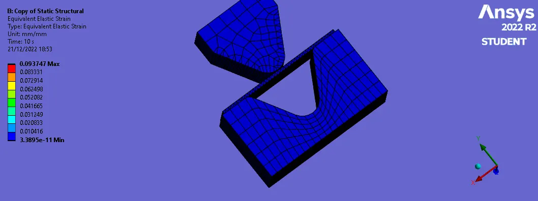
Equivalent elastic strain
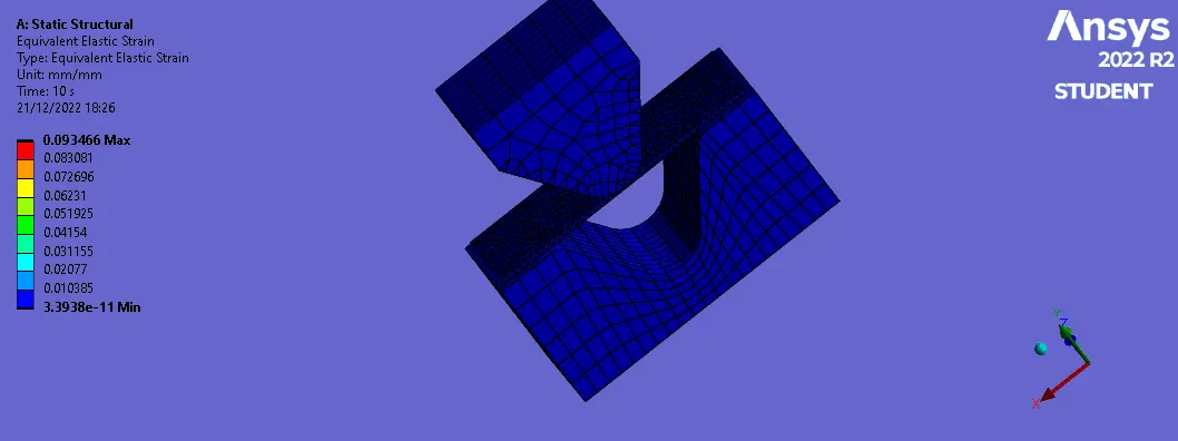
CASE 2
Copper Alloy NL :
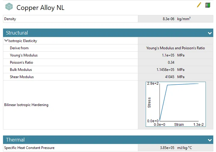
Directional Deformation
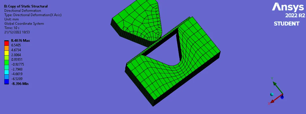
Equivalent Stress
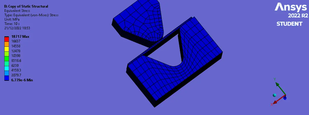
Equivalent elastic strain
CASE 3
Magnesium Alloy NL
Directional Deformation
Equivalent Stress
Equivalent elastic strain
So here we can see the Equivalent stress is changing as we change the material. Same with the equivalent elastic strain its changing as we change the material.
- Only the Directional deformation is not changing.
CASE 2: With the material as Aluminium Alloy, change the friction coefficient to 0.19 and run the analysis as mentioned in Case 1. Compare the results with that in case 1.
- Now we will change the friction coefficient to 0.19 and comapre it with friction coefficient of 0.1
Directional Deformation
Equivalent Stress
Equivalent elastic strain
- Here as we change the coefficeint of friction increase we can see the change in equivalent stress.
CASE 3: Refine the mesh on the plate such that it doesn't cross the academic limit. With Aluminium alloy as material, run the analysis as in Case 1 and compare the results.
- In this we will change the meshing size as 2 mm and perform the simulation.
Directional Deformation
Equivalent Stress
Equivalent elastic strain
- Here as we increase the element size we can see that the stress is decreased.
RESULTS:
- All the required result are showed in above images .
- Also the comparison is between all the cases is done too.