Week 3 Sheet metal Bending challenge
Objective: 1.To run the simulation of sheet material choosing three different materials i.e Magnesium Alloy NL, Copper Alloy NL, Aluminum Alloy NL.
- To run the simulation by comparing the results of Aluminum alloy with two different coefficient of friction as 0.1 & 0.19.
- To run the simulation by comparing two different mesh sizes of 1mm & 0.7mm & keeping the sheet material as Aluminum alloy NL.
Case Setup & Execution: Initially open the Ansys Workbench & load static structural for analysis.
Following steps are as follows:
- Load the geometry of Punch Die & sheet. Open the same in space claim and check the geometry.
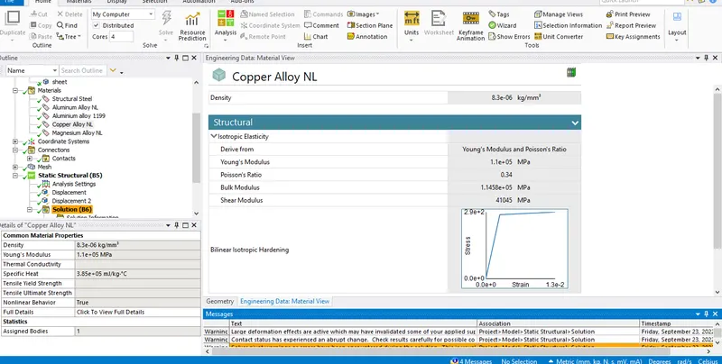
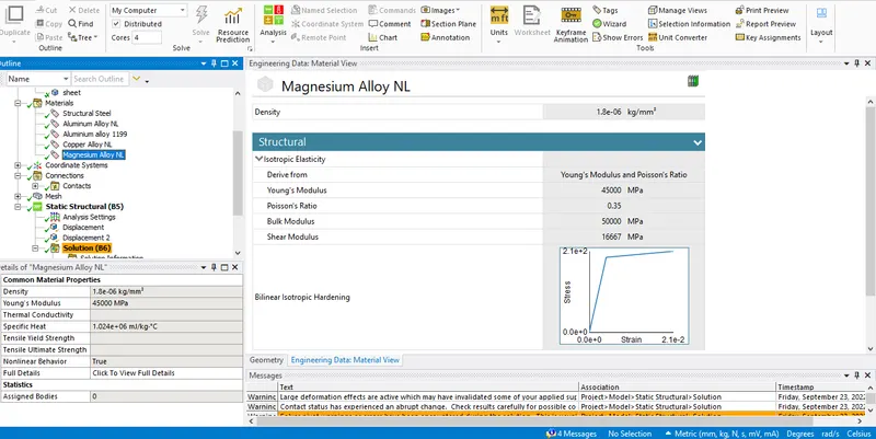
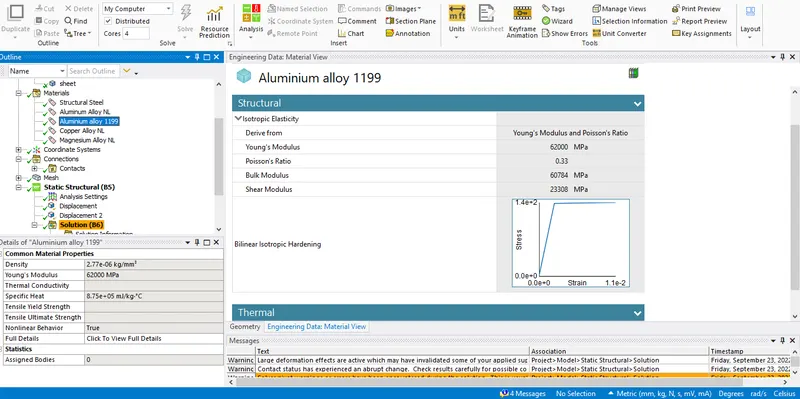
- Now open Engineering data & load three different Non-linear material such as Magnesium, Aluminum & Copper alloy.
- Update the model and rename the Workbench file as required. Open & Edit the file in Graphical User Interphase.
- Rename all the parts & choose the material as required for various simulation.
- Delete all the contacts & insert manual contact region. Select three faces of the Punch as contact & upper face of sheet as target.
- Insert another contact. Select bottom surface of sheet as contact & upper face of die as target. Select the above two contacts and provide a frictional value of 0.1. Change the behavior to asymmetric. Formulation as Augmented Lagrange. Interface treatment to add offset ramping effects & normal stiffness as 0.1.
- Now moving to mesh .Insert sizing, add 4mm of mesh to Punch & die. Next add 1mm sizing to sheet & other contact faces of punch & die. Insert patch conforming and select method as tetrahedrons.
- Now moving to analysis setting add no of steps as 10. Select all the steps add large deflection as on, Stabilization contact, Energy dissipation as 0.1, Solver type to direct.
- Now add displacement to Punch by selecting the top three faces and add displacement from -0.5 to 13.5 till 8 steps and then reducing the same to -8 in next three steps. The returning of punch is done to displace it in the reverse direction. Select x & y direction as tabular and set them as zero.
- Next again add displacement to the die and add tabular to all three axis also add displacement of -1.5 & -3 mm to last two step in y direction . This enable the die to move backwards as after the punch & die operation.
- We can add one more displacement and select the four faces of sheet & provide tabular data and set zero value in X & Z direction.
- Now in the solution add various stress, strain, deformation as required and Hit solve to proceed for the simulation to run and execute the results for comparison.
Results -
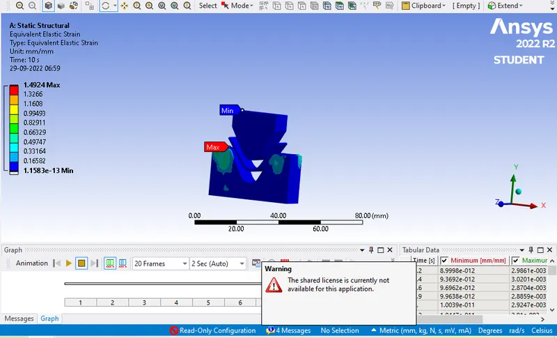
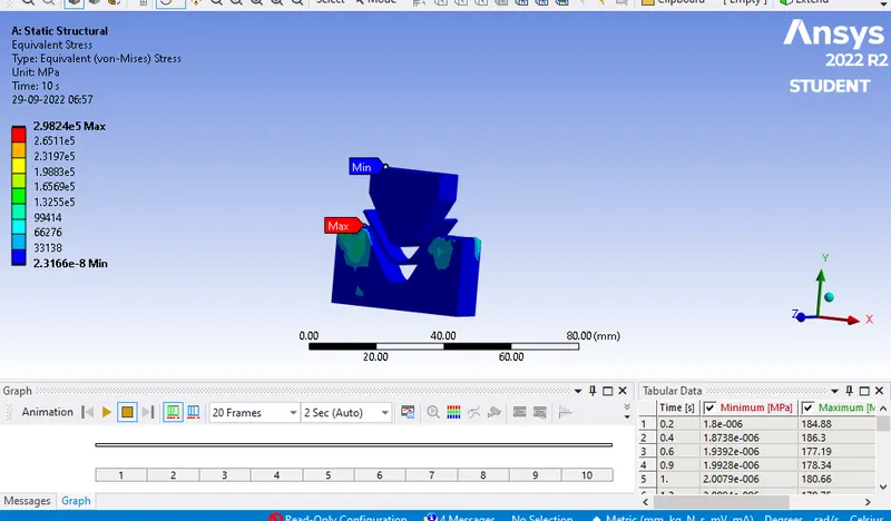
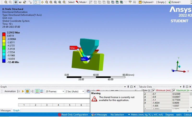
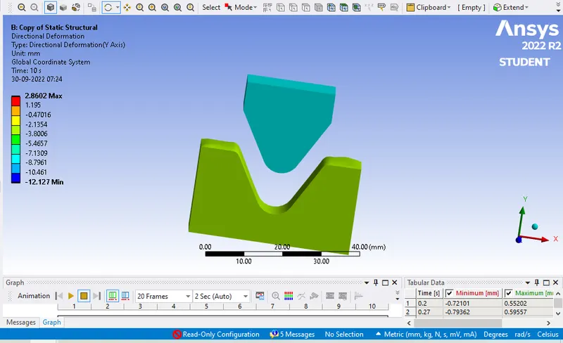
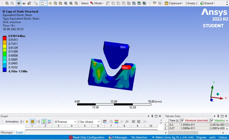
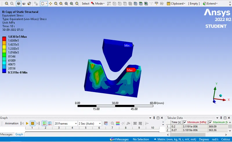
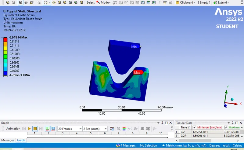
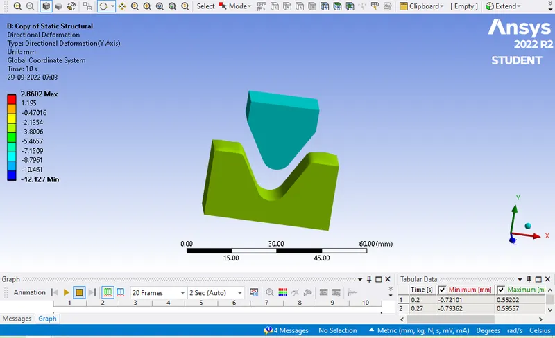
Case 1: In this case we are comparing three different material in sheet metal bending & comparing various solution such as stress strain & total deformation. Following results are as follows.
|
SR NO |
MATERIAL |
EQUIVALENT STRESS (MAX) MPA |
EQUIVALENT STRAIN (MAX) |
TOTAL DEFORMATION IN ‘Y’ |
|
1. |
Aluminum alloy Non linear |
2.9824e^5 |
1.4924 |
2.2932 |
|
2. |
Copper alloy Non linear |
1.8303e^5 |
0.91814 |
2.8602 |
|
3. |
Magnesium alloy Non linear |
2.0355e^5 |
1.018 |
1.8081 |
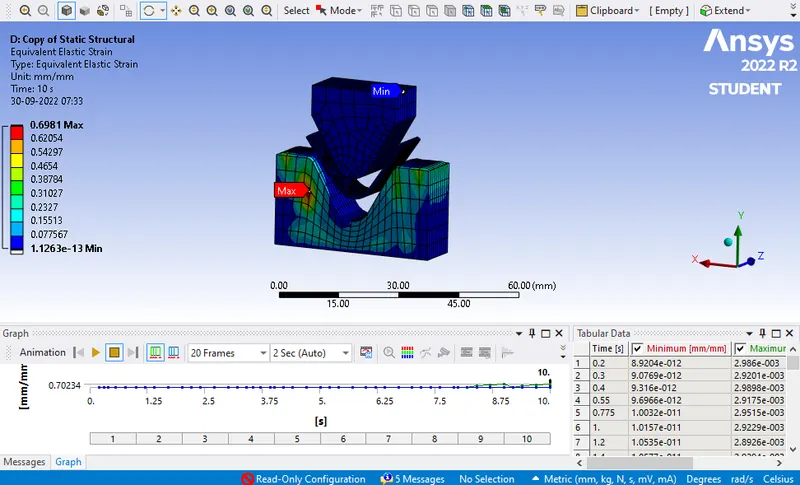
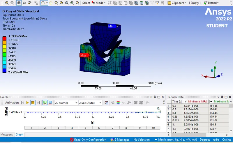
Case 2: In this case we are changing the friction value from 0.1 to 0.19 and comparing all the results of various solution.
|
SR NO |
Material |
Coefficient of Friction (µ) |
Equivalent stress (Max) Mpa |
Equivalent strain (Max) |
Total Deformation in ‘y’ |
|
1. |
Aluminum alloy Nl |
0.1 |
2.9824e^5 |
1.4924 |
2.2932 |
|
2. |
Aluminum alloy Nl |
0.19 |
1.3938e^5 |
0.6981 |
2.4358 |
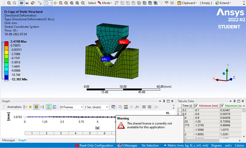
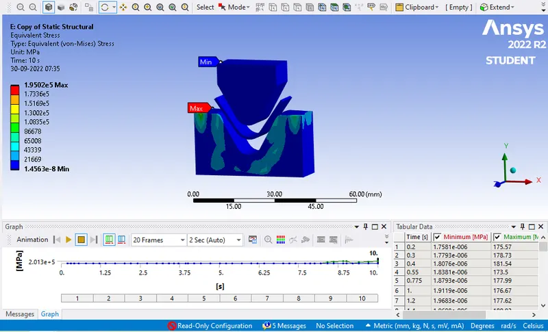
Case 3: In this case we are comparing the results of Aluminum sheet with two different mesh sizes. Following data on various solution are as follows.
|
SR NO |
Material |
Mesh Size of sheet |
Equivalent stress (Max) Mpa |
Equivalent strain (Max) |
Total Deformation in ‘y’ |
|
1. |
Aluminum alloy Nl |
1mm |
2.9824e^5 |
1.4924 |
2.2932 |
|
2. |
Aluminum alloy Nl |
0.7mm |
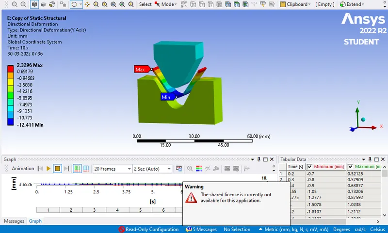
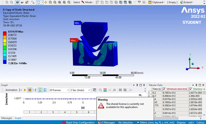
1.9502e^5 |
0.97619 |
2.3296 |
Conclusion:
Case1: In this we can observe that maximum stress is observed in the material Aluminum alloy following Magnesium & Copper. Similarly strain generated in Aluminum is more than Magnesium & Copper. The above all results completely depend on the elastic properties & boundary condition applied. Next looking at total Deformation the maximum deformation is seen in Copper alloy NL than the other two material. Observing all the values it can be easily said that Copper being one of the best material for the sheet metal bending. But definitely if we look for the cost then aluminum is cheap and easily available. So material selection will be done on various parameters.
Case 2: In this case we have used material as Aluminum alloy and changed the coefficient of friction from 0.1 to 0.19 and now comparing the results. While comparing it has been observed that keeping the friction value low to 0.1 increases the stress, strain and deformation value. While material with higher friction values develops less stress and strain.
Case 3: In this case we have refined the mesh size of sheet to 0.7mm. This is the maximum limit that can be achieved to run the simulation in student version. From the results it can be observed that finer the mesh size the more accurate and precise results are been generated. Reducing the mesh size helps the solver to solve for more number of elements and generate accurate results.
Note- All files are attched with above for the reference. Simulation file is attached in required format.