Week 3 Sheet metal Bending challenge
Aim: To simulate the sheet metal bending in ansys workbench.
Objective:
Introduction:
Sheet metal bending is an effective way of making products with different shapes used for different processes. It guarantees simplicity and it is an efficient way of forming new products. Here, you will know about sheet metal bending, its importance, and the methods needed for the process.
Sheet metal bending is an operation that involves using forces to change the shape of a sheet. This is done to achieve the desired form or shape needed for a manufacturing process. The external force used alters only the external features of the sheet. However, parameters of the one type of sheet metal such as length and thickness remain the same. The malleability of the sheet metal further allows it to undergo various shaping processes. Sheet Metal Bending is a process by which sheet metal can be deformed when applying force to the subject, which causes it to bend at an angle and form the anticipated shape, which often results in it being in a ‘V’ or a ‘U’ shape. A press brake is a tool used in order to bend sheet metal and uses a punch and die to do this.
Procedure:
- After opening Ansys Workbench, use static structural as the mode of analysis for simulation.
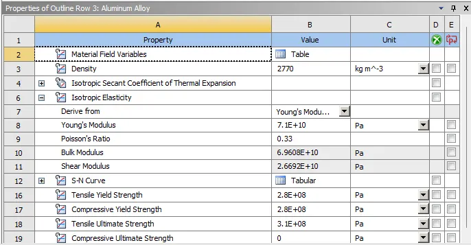
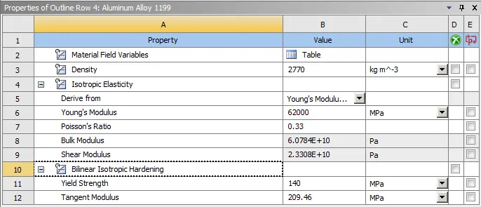
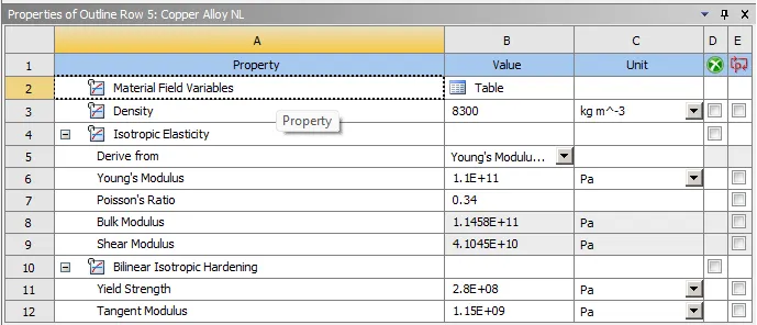
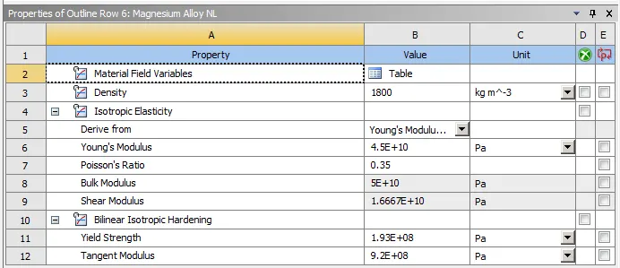
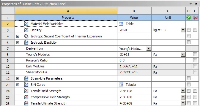
- Now, add materials as structural steel, aluminium alloy, alluminium alloy 1199, copper alloy NL, magnesium alloy NL from the engineering data project menu.
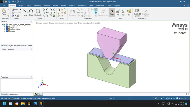
- Import the model provided and check the geometry in the Ansys Spaceclaim for any abnormalities.
- Assign material as structural steel to the punch and die; and assign aluminium alloy 1199 to the sheet metal.
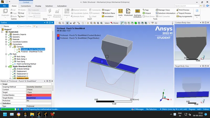
- Create contact frictional joints as shown below:
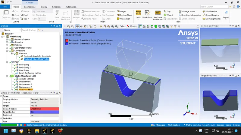
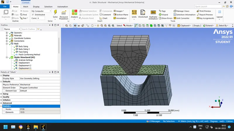
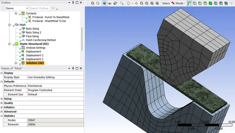
- Mesh all the components with default element size. And refine mesh on the faces which are coming in contact for our study using sizing of 2mm. Use tetrahedron method for sheet metal.
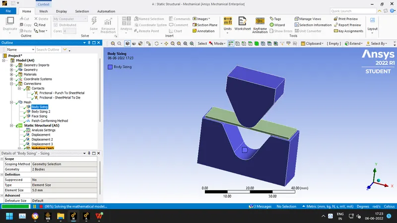
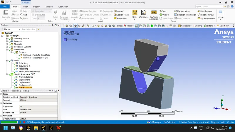
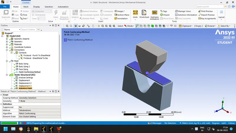
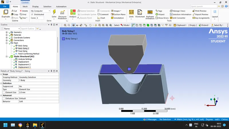
The final mesh obtrained is
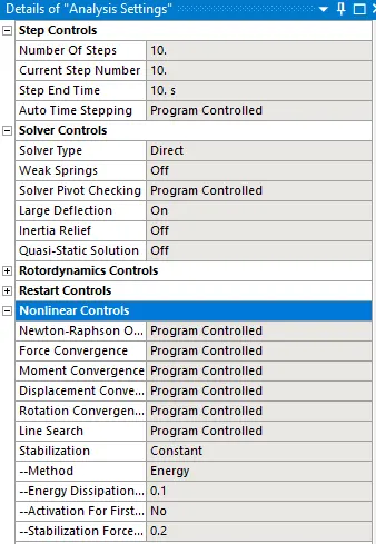
- Following analysis settings have been set for the simulation for 10 steps:
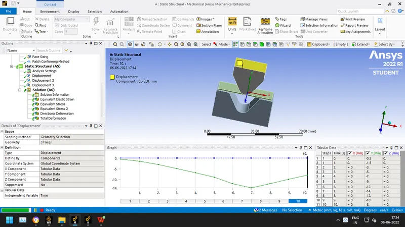
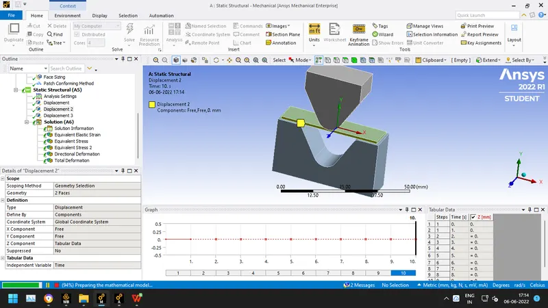
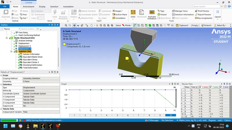
- Now adding displacements to the components as shown below:
Punch in Negative Y direction for 14 mm where it is pushed down and pulled up back again; relief of 3mm is provided for the die.
- Now, Insert total deformation, equivalent stress, directional deformation, equivalent elastic strain.
- Finally following solutions have been obtained after running the simulation for Sheet Metal Bending:
CASE 1: Results for aluminium alloy 1199, copper alloy NL, magnesium alloy NL as the material:
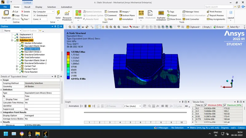
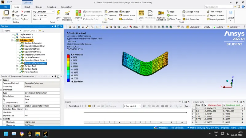
- Results for Aluminium Alloy 1199
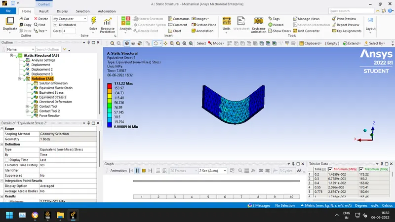
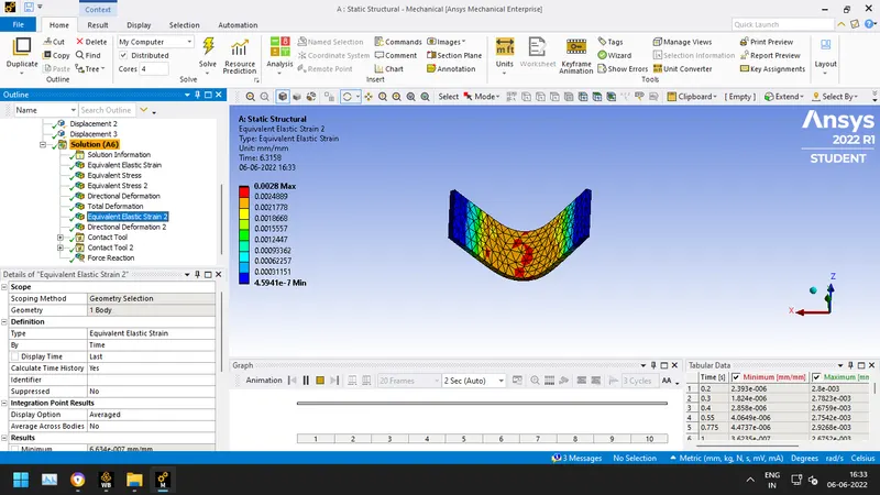
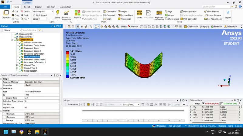
- Results for Copper Alloy NL
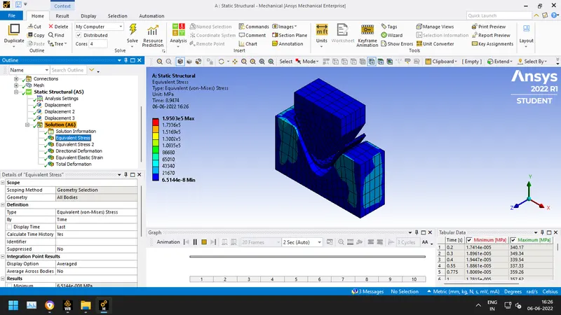
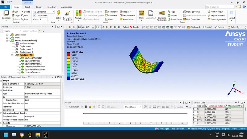
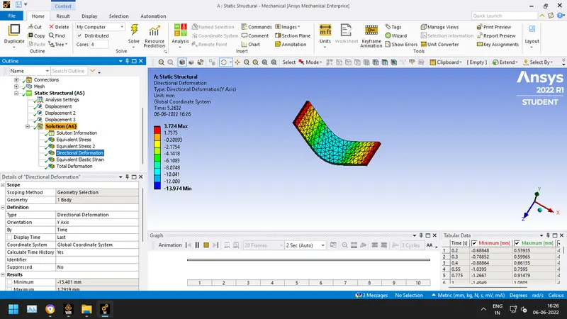
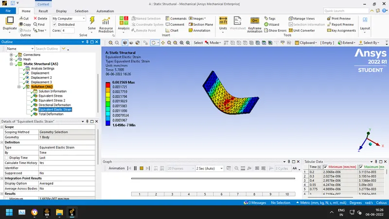
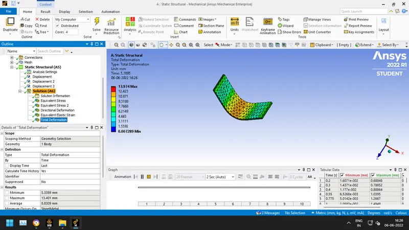
- Results for Magnesium Alloy NL
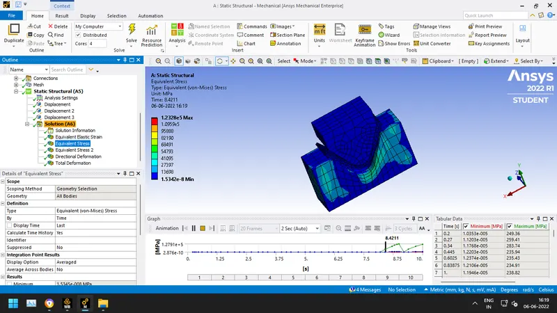
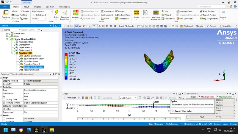
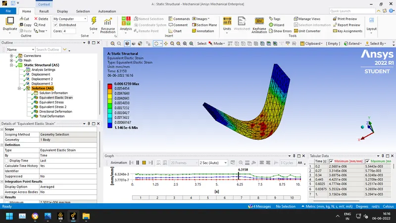
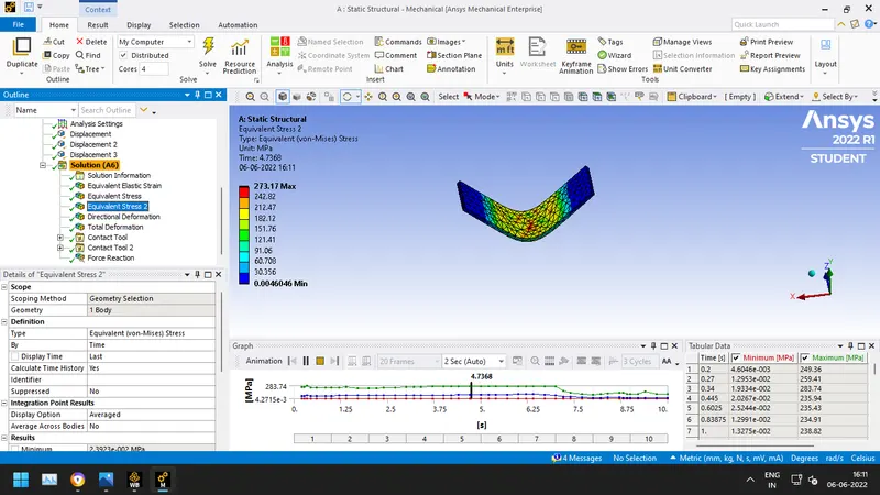
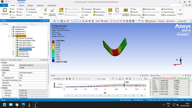
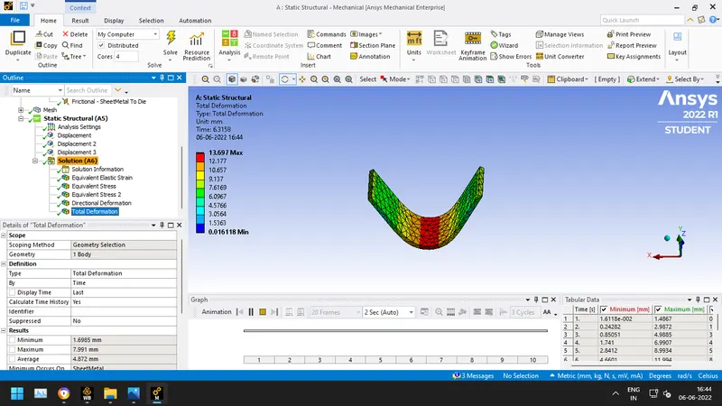
CASE 2: Results for Frictional Contacts with frictiion of 0.19 and aluminium as the material:
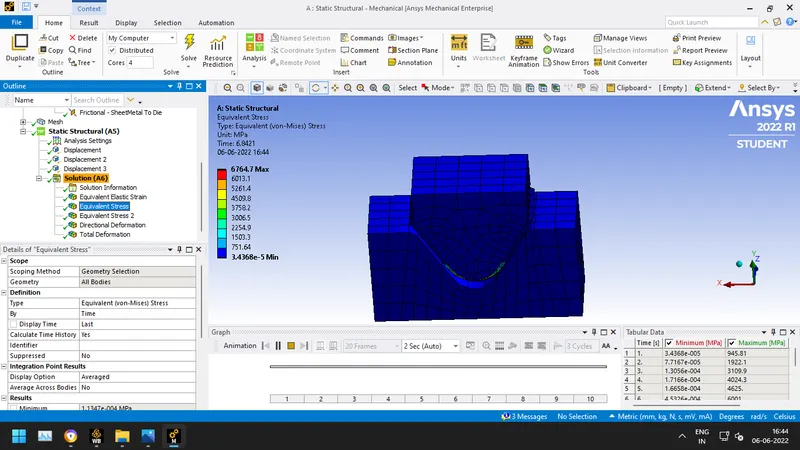
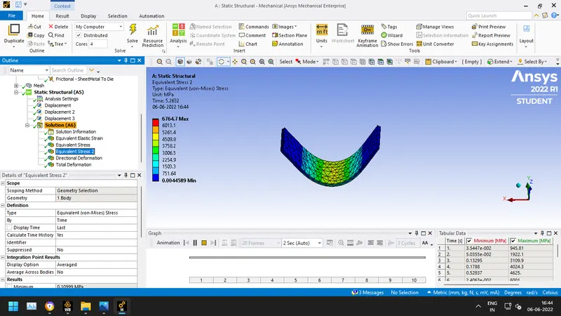
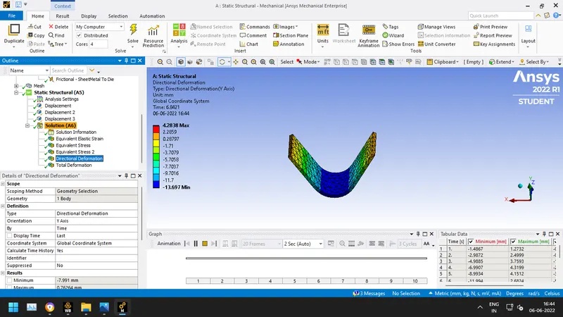
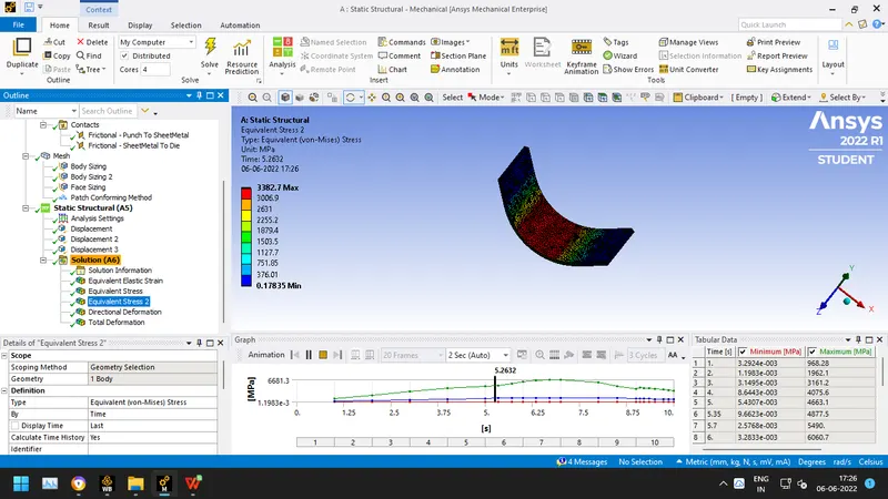
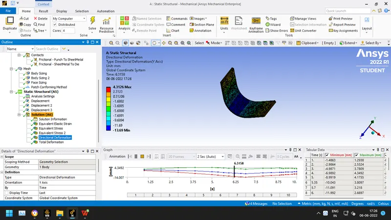
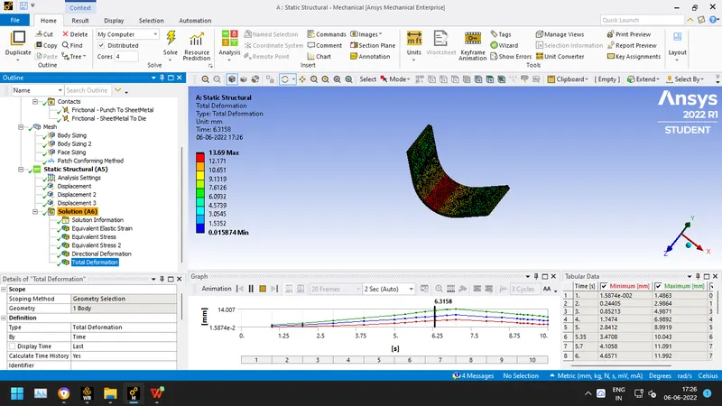
CASE 3: Results for Refined Mesh with 0.5mm Element Quality on Plate & Frictional Contacts with friction of 0.19 and aluminium as the material:
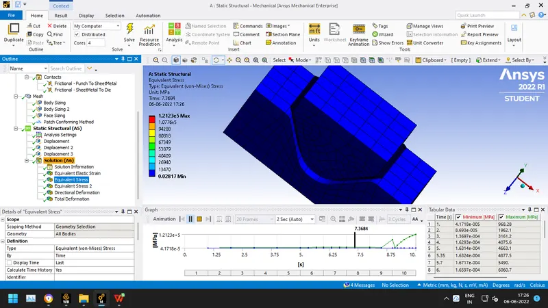
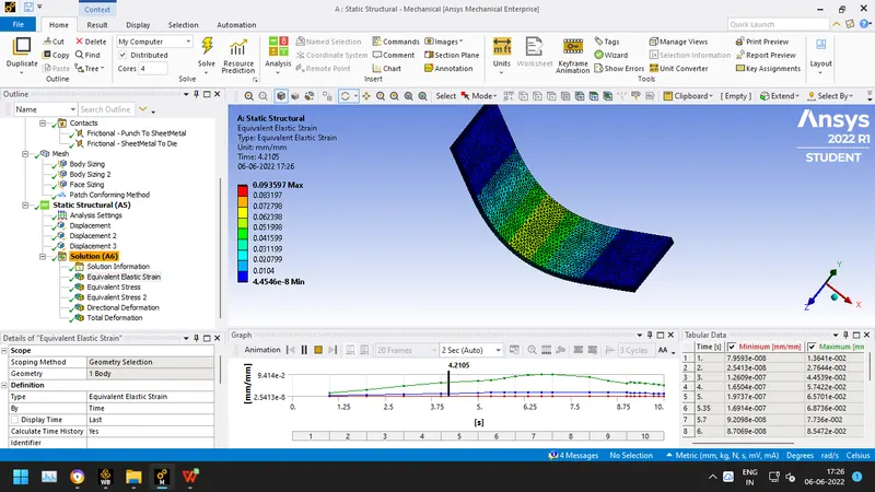
Results are as follows:
- Conclusion:

From the above results,
For Case 1 we can say that the max stress of 387.23 MPa is obtained for Copper Alloy NL with less directional deformation of 3.724. And the least stress of 173.22 MPa is obtained for Aluminium Alloy 1199 with 8.416 mm of directional deformation. So, we can say that the best material among the three is aluminium alloy because less stresses are induced and the deformation is also maximum.
For Case 2, when adding frictional contacts from 0 to 0.19 there is a very high value of stress induced in the sheet metal and the directional deformation is 4.2mm. The strain also increases to very great great extent when compared with case 1.
For Case 3, when the element is reduced to 0.5 mm from 2mm, more accurate results are obtained. The max stress obtained is 3382.7 MPa and the deformation observed is 4.312mm.