Week 3-Meshing of Hood Challenge
For this task i have started my work for importing the file. after opening the model. i examined the model is any faulty surface is there or not.
Then i did the auto cleanup the model because it has lot of topology lines. so every lines is not necessary to consider for mesh only feature based lines are needed for better mesh to capture he geometry. for removing unnecessary lines i am suppressing unwanted lines so for to do this i used auto cleanup tool form geometry tab.
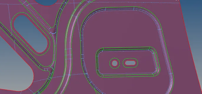
For better meshing i also offset the lines from the features liked the key hole, oblong shape and others. to do this i used the option washer lines with 5mm. from the quick edit tool.
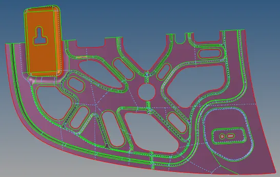
As I can analyze this geometry is symmetric. except the middle key hole surfaces. for considering the symmetric model it can save my time for the meshing so i will i have made another component so that i can extract and move the asymmetric surfaces in the created component.
Then i cut the geometric by selecting the surface edit tool ---trim with surface/plane by defining the Base point and the axis of the plane we can define and cut our geometry accordingly.
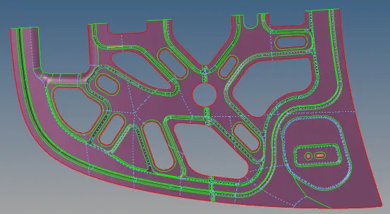
After setting the geometry i have started to create the meshing with 5mm global size with mixed element type. for meshing i also created another components and named as 2d and unsymm for my ease. i also set meshing quality criterion from the given parameters. i created mesh in different component for the asymm surfaces. why because in the end i can reflect the symmetric part mesh only.
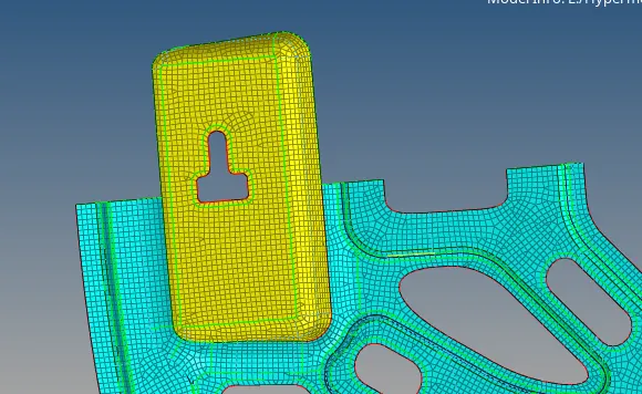
creating whole meshing for the whole geometry i checked the quality criterion to check which elements are failing. so all failed elements are corrected by remeshing to particular at failing regions, element cleanup tools.
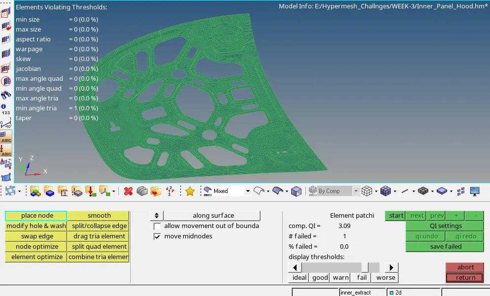
So i have checked all the parameters like warpage, min length, max length, min angle, max angle (Quad, Tria) etc. all the failing elements are 0. at every quality parameters.
Then i will reflect the meshing to another side. for do this i used reflect option using duplicate elements in the original component and provide the axis and base node. it is a best practice to check the equivalence the node after reflecting elements. because every time when we do the reflects element's there will always remain a gap. Node connectivity should be there for analysis.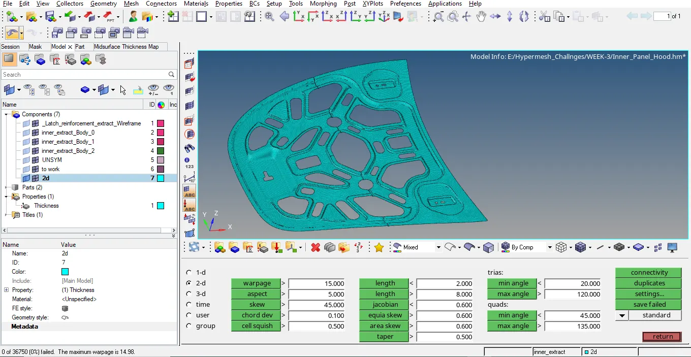
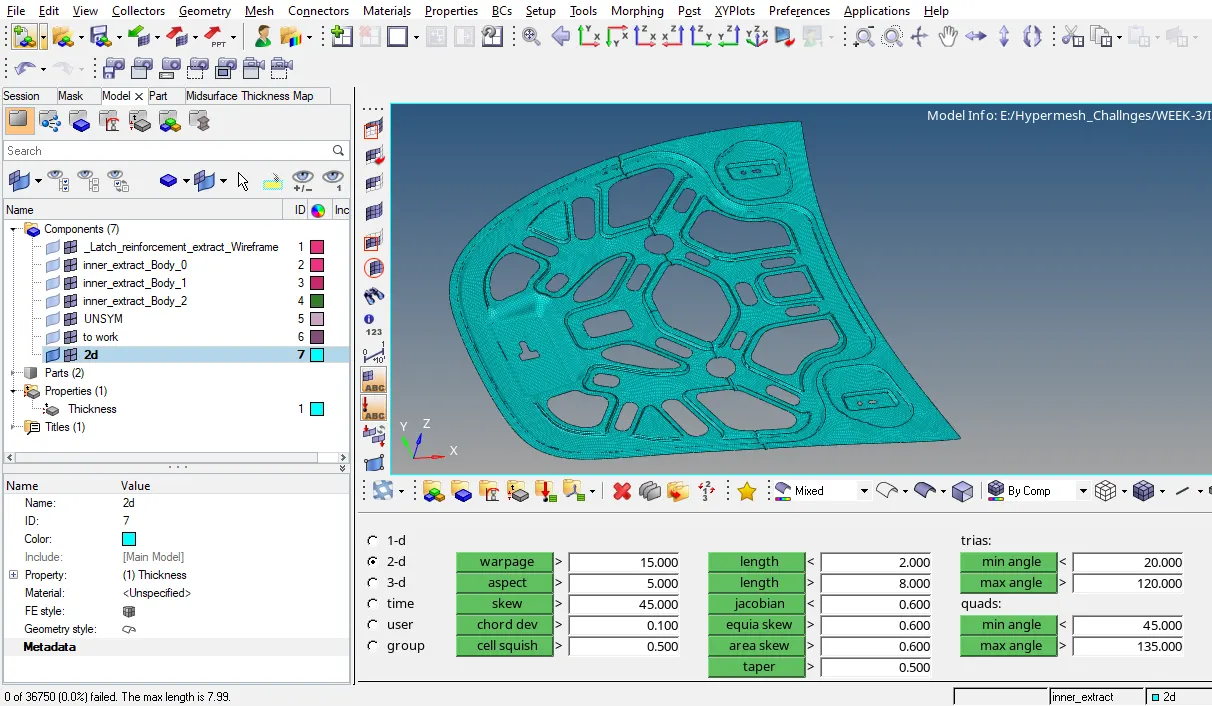
In the last i will move all the elements i a single component named as 2D. I need to give the thickness i have to created a new property---shell section--thickness-0.75mm. Then i assigned this property to all the elements.
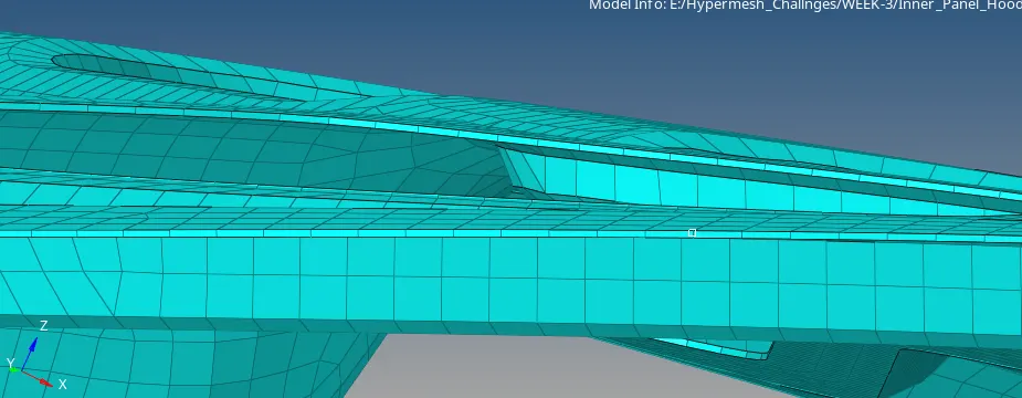
Now go to '2D Detailed element representation' to see the thickness to meshed elements.