Week 3 - Geometry simplification of an Electronic enclosure assembly
JORGE LOZANO
Electronic Cooling Simulations using ANSYS ICEPAK
Geometry simplification of an electronic enclosure assembly
Objective:
- The power board assembly is provided for this assignment. Students should create the workflow in ANSYS workbench and import the CAD model into space claim.
- Use space claim commands to defeature the enclosure
- Use Icepack commands to convert CAD shapes into Icepack primitive shapes.
- Save converted geometry
- Open saved converted model into Icepack
- Check the geometry in icepack
- Modify components in icepack to define the correct physics
Introduction
One of the advantages of Icepak is in its interface consistency with the rest of the Electronic Desktop (EDT) products. This not only results in a slick modern appearance but also provides a very familiar environment for the electrical engineers and designers who typically use the other EDT tools. While they may not already be intimately familiar with the physics and setup process for CFD/thermal simulations, being able to follow a very similar workflow certainly lowers the barrier to entry for accessing useful results. Even if complete adoption by these users is not practical, this same environment can serve as a happy medium for collaboration with thermal and fluids experts.
ANSYS ICEPAK PACKAGES
Icepak is available as part of the Premium and Enterprise product suite. Listed below is a sampling of capabilities at each level that are most relevant for designing electronics cooling applications.
ELECTRONICS PREMIUM ICEPAK:
- All Icepak Solvers
- Mechanical Thermal and Modal Solvers
- ECAD and MCAD modeling and translation
- Advanced Circuit Analysis
- Electronics Pro 2D
ELECTRONICS ENTERPRISE:
- Design of Experiments
- Ansys SpaceClaim Design Modeler
- Electronics Premium (Icepak, HFSS, SIwave, Maxwell, Q3D Extractor)
- The complete list of the Electronics Product Package contents is available in the table below.
Process
Given this geometry, the first step is to drag into the workspace the Icepak module, and import the CAD file, deleting the bolts, fillets, washers unwanted. Inspection of the initial CAD file is critical to define the following steps and process taken place.
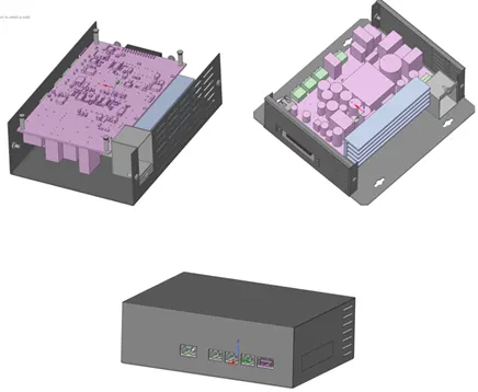
Having seen the CAD file, there’s a cleaning process which must take place, splitting several jointed parts into individual parts within a group seen in the following left image, each part hast to be analyzed individually unless is already and known the effects of efficiency in the simulation when simulated together or separate.
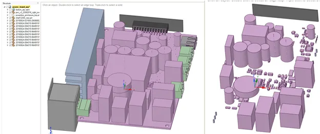
In the Ice Pak, Ice Pak Simplify selection, each element will be given 3 levels of geometric accuracy, the higher the level the higher the refinement in the geometry curves, the second level eliminating fillets and simplifying the element, and the firs level having cylinders, cubes, and simple geometries.
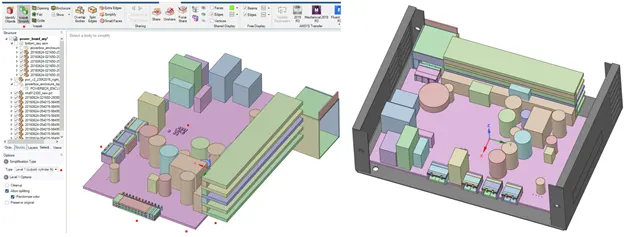
As seen, the heat shrink and other components to present a simplify geometry level, the software must separate each individual geometry into several parts to define a structure orthogonal mesh, having in the following image the inner parts processed into Ice Pak components. Having the red dots indicating the parts of which the simplification will take place.
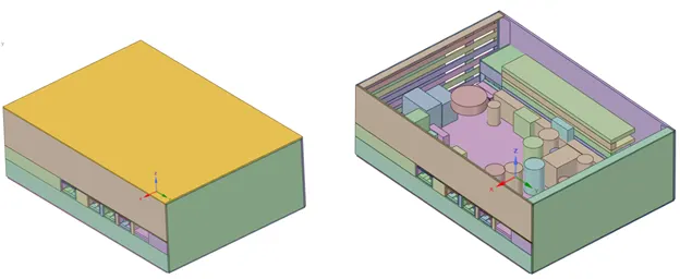
Once it’s done, the following step is to generate a grill for the external plate and simplify into Ice Pak elements each part of the assembly, as seen in the following image not all components were selected into the Id for Ice Pak, but it can be done individually according to the need of the simulation.
Conclusions
As far as the geometry cleaning process it is done, although the following step is to open the geometry into Ice Pak module and see all objects and elements generated, to validate the work done and proceed to generate a mesh
Reference