Week 3- Geometry cleanup and Mid-surfacing
PROJECT 1 : PERFORMING GEOMETRY CLEANUP AND EXTRACTING MID SURFACE FOR THE GIVEN TUBE MODEL.
AIM / OBJECTIVE : To peform a geometry cleanup and to extract the mid-surface for the given tube model. Also along with that provide a sharing connection option at the tube joint locations.
PROCEDURE :
Before getting into the geomery cleanup let us see how our model looks like.
MODEL BEFORE GEOMETRY CLEANUP AND MID-SURFACE EXTRACTION :
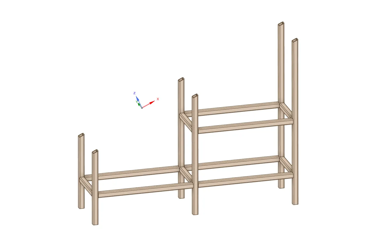
FIGURE 1 : REPRESENTS THE ACTUAL (OR) ORIGINAL CAD MODEL.
STEP-1 : Now we have our original CAD model of the tube before geometry cleanup and extraction of mid-surface.
NOTE: Goemetry cleanup is basical process done before extracting midusurface and meshing. This process is done so that the duplicate surface can be eliminated, surfaces can be stitched, gaps can be filled, edges can be shared. We do this to reduce our time during the meshing and analysis process and this is known as defeaturing of the CAD model. But be careful while defeaturing the model because some removal of the parts or features may adversely affect the analysis part and can give us poor results.
STEP -2 : In this step we will start identifying the basic defeaturing or the geometry cleanup options : Stitching the edges,filling the gaps and find the missing faces if any and then also search for extra edges and duplicates if any. To do this go to repair option tool box and there you can find these options.Find the below attached image to pick the tools.
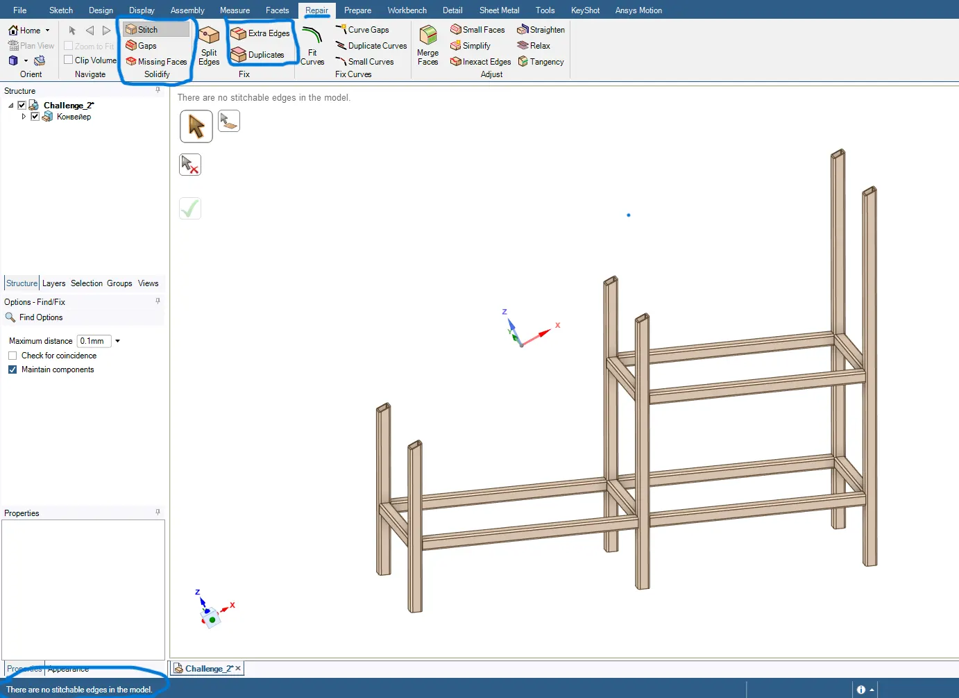
FIGURE 2 : REPRESENTS THE SELECTION OF THE REPAIR AND STITCH OPTION.
In the above image you can find the repair option in the toolbox and then find the following options as mentioned earlier marked with blue sketch. When we pick the first option i.e., the stitch option you can find below there are no stictchable edges in the model which means our model is free of stictches and no surfaces are found. Now you can move onto the next option "gaps" and repeat the same.
STEP-3 : You can click on the "gap" option and if there are any please fix it.
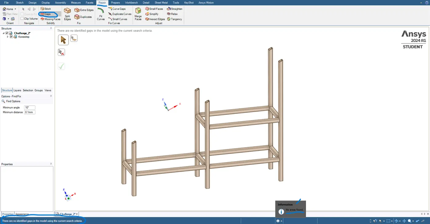
FIGURE 3 : REPRESENTS THE SELECTION OF GAP OPTION.
In the above image you can see there are no gaps found.
STEP-4 : You can click on the "missing face" option and if there are any please fix it.
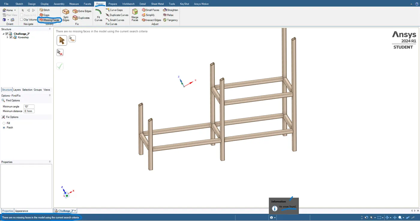
FIGURE 4 : REPRESENTS THE SELECTION OF THE MISSING FACES OPTION.
In the above image you can see there are no mssing faces found.
STEP-5 : You can click on the "extra edge" option and if there are any please fix it.
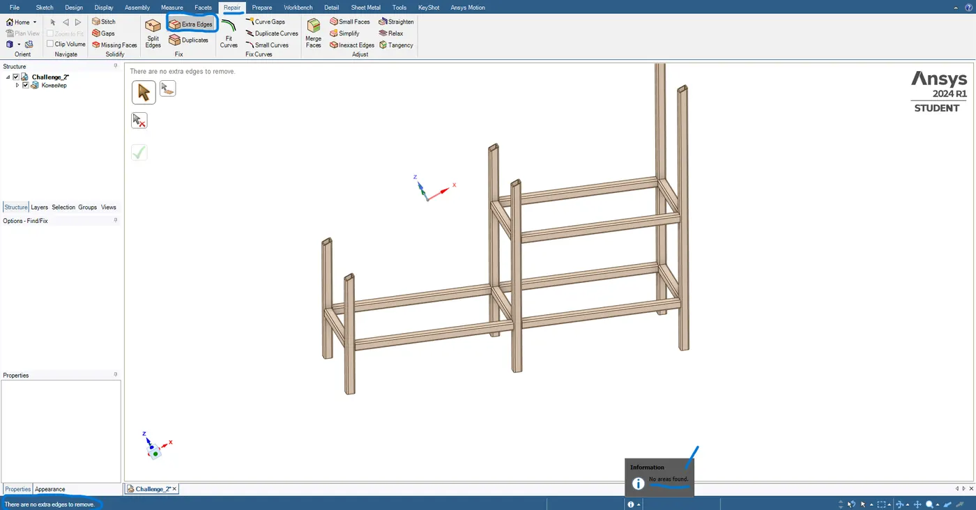
FIGURE 5 : REPRESENTS THE SELECTION OF THE EXTRA EDGE OPTION.
In the above image you can see there are no extra edges found.
STEP-6 : You can click on the "dulpicate" option and if there are any please fix it.
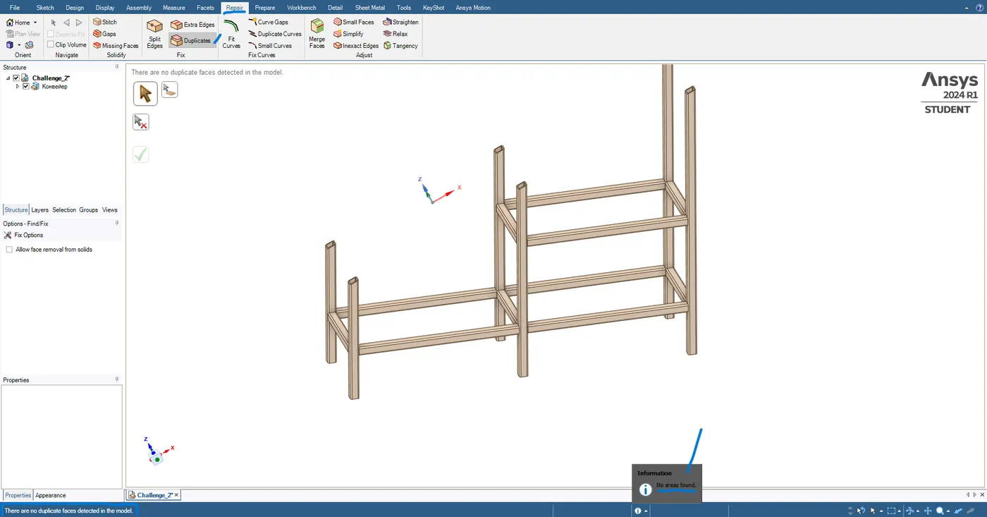
FIGURE 6 : REPRESENTS THE SELECTION OF THE DUPLICATE OPTION.
In the above image you can see there are no duplicates found.
STEP-7 : Now we have done the geometry cleanup for the given tube model and now we have to extract the mid-surface but before extracting, let us first split the whole model into individual tubes. To do that use the split option from the tool box "design". There you will be able to find the split body option. Then click on the body which you want to split. Below the yellow colour marked is the body which we want to split.
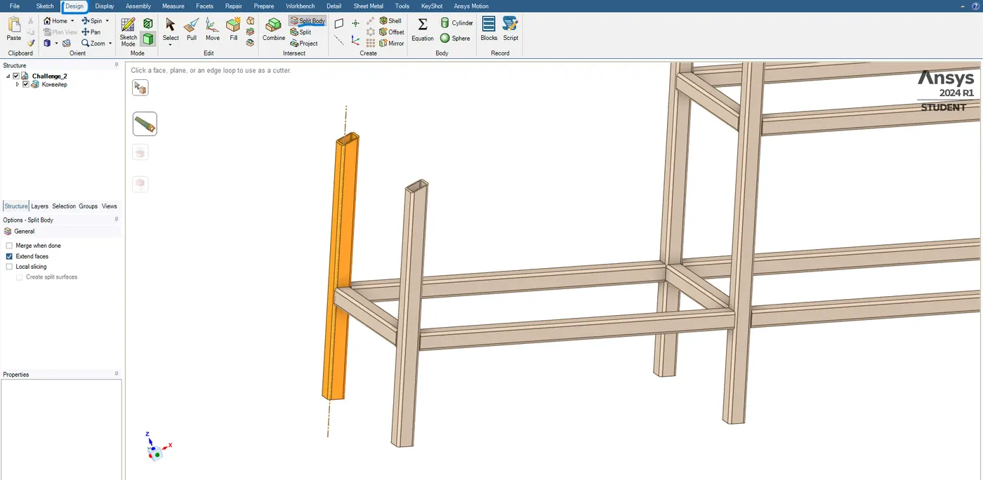
FIGURE 7 : REPRESENTS THE SELECTION OF THE SPLIT OPTION UNDER DESIGN TOOL BAR.
STEP-8 : Then click on the cut option to cut the body. Also select the plane in which you want to split as per below image.
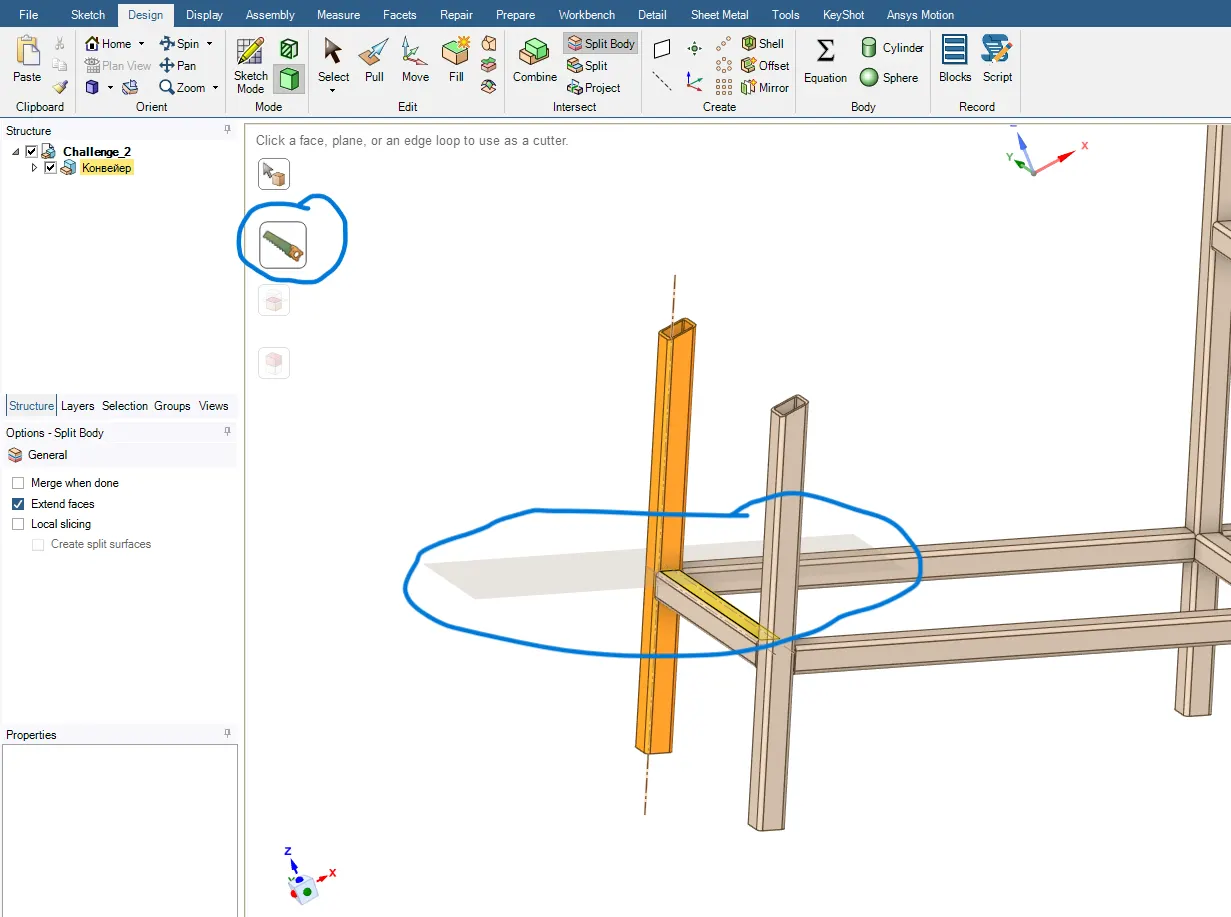
FIGURE 8 : REPRESENTS THE SELECTION OF THE CUT OPTION TO CUT THE BODY.
STEP-9 : Below is the final image of the splitted body into two halves.
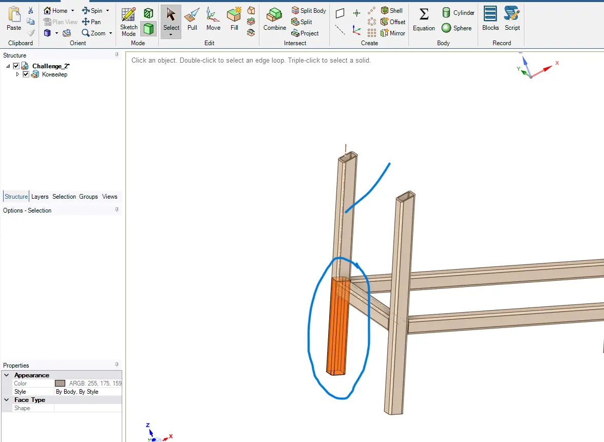
FIGURE 9 : REPRESENTS HOW THE COMPONENT (OR) THE BODY IS SPLITTED.
Above blue mark represents the body getting splitted into two halves. Now do repeat the same for the whole model. In this case only vertical tubes are getting splitted and horizontal tubes dont since they are already connected together.
STEP-10 : Here is the final isometric view of the splitted body.
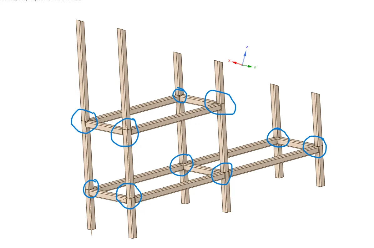
FIGURE 10 : REPRESENTS THE ISOMETRIC VIEW OF THE SPLITTED MODEL
STEP-11 : After completion of the splitting of the tubes we can go for midsurfacing of the tubes individually or in a group. To do midsurface go to the prepare option from the toolbox. Then, click on the use range option and mention the min and max thickness of the material. This option is very beneficial when the components are more or complex and of uniform cross section.Use selected faces can be used when there are only few components.
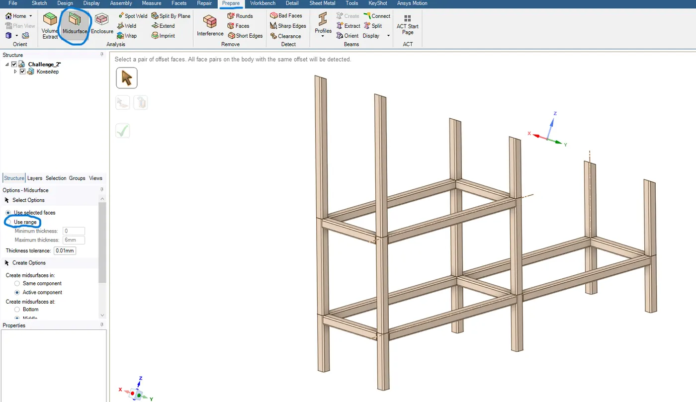
FIGURE 11 : REPRESENTS THE SELECTION OF MIDSURFACE OPTION UNDER PREPARE TOOLBAR
STEP-12 : Now measure the thickness of the tube using the measure tool from the tool box and note the thickness.Use ctrl and click on the two lines you want to measure or you can press E as a shortcut to measure and it shows 6mm.
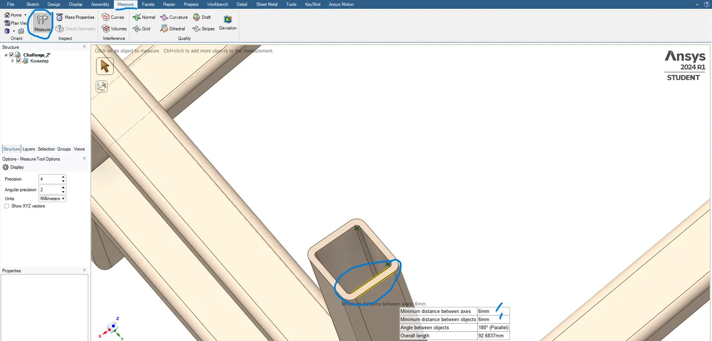
FIGURE 12 : REPRESENTS THE MEAUSUREMENT OF THICKNESS USING MEASURE TOOL.
STEP-13 : Now select the whole model by creating a window by clicking and dragging the left mouse button to the right direction.
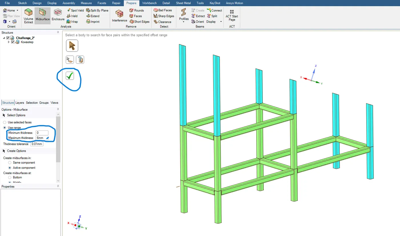
FIGURE 13 : REPRESENTS THAT THE MODEL IS READY FOR MIDSURFACING
STEP-14 : Now create the midsurfaces under the "active component" category.
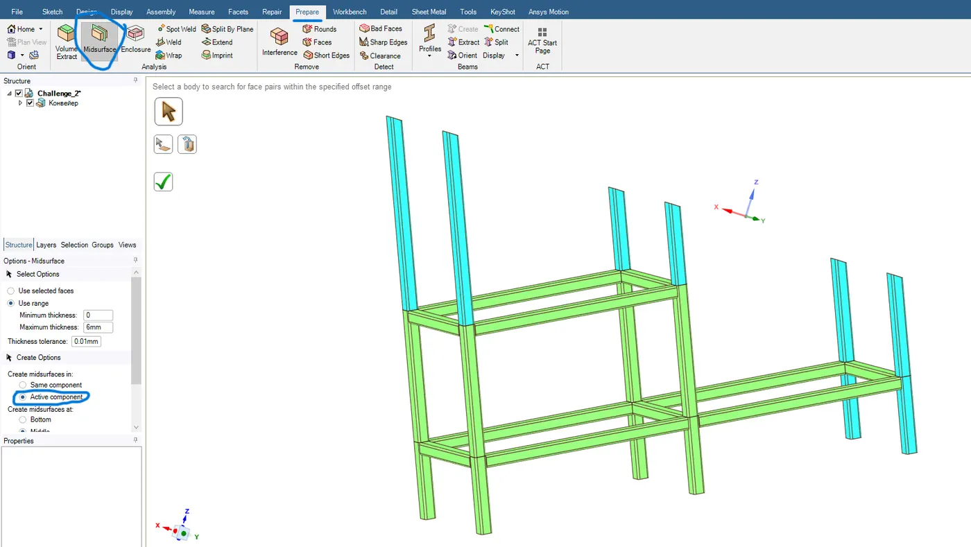
FIGURE 14 : REPRESENTS THE SELECTION OF THE ACTIVE COMPOENENT.
STEP-15 : Now midsurafce is extracted under the active component category. In the below image click on the surface or the edge next to the midsurface so that the midsurface is extracted separartely. Below is the final image of the Midsurafce extraction of the tube model. Also you can see the midsurface extracted is represented as components on the left side under the design tree.
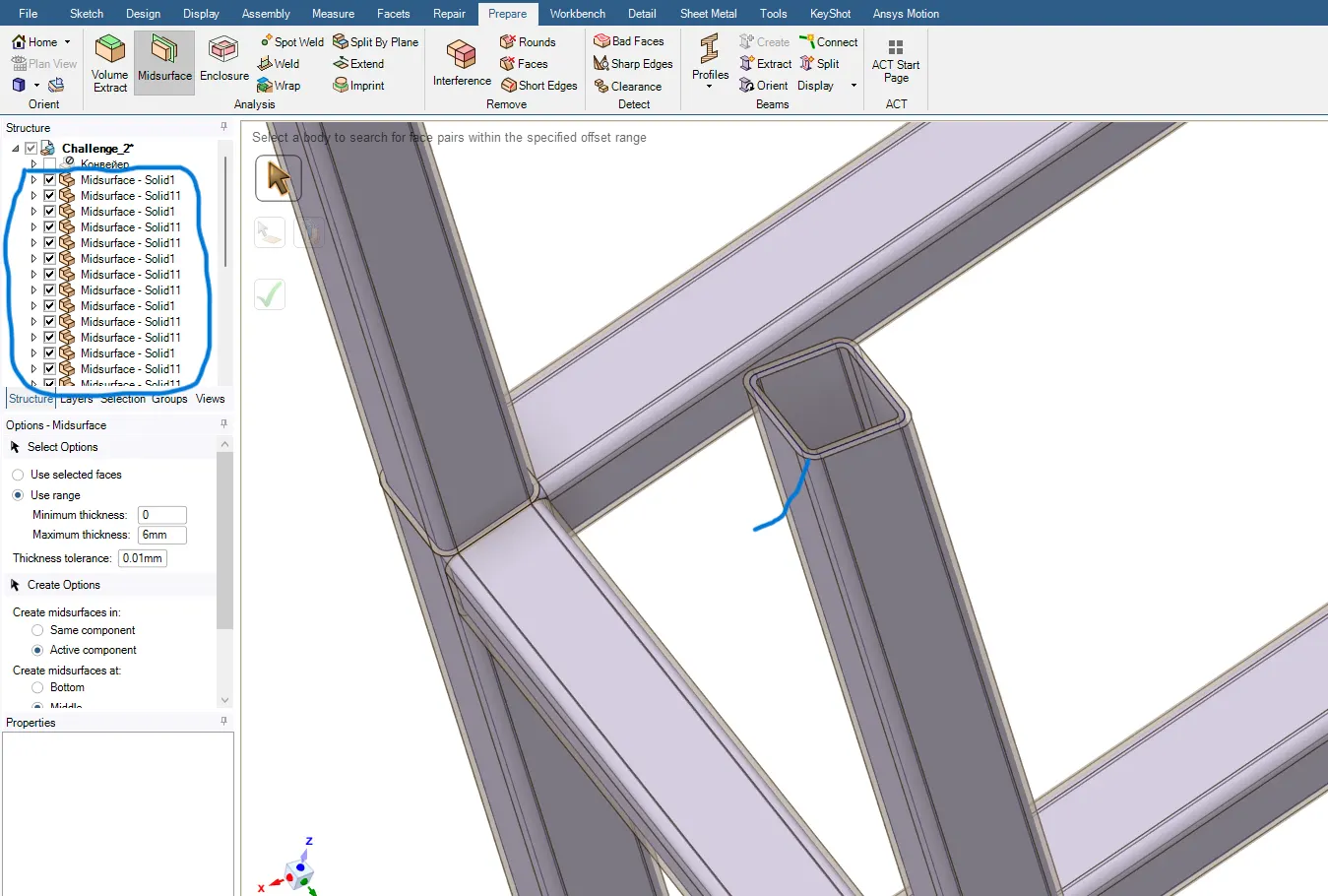
FIGURE 15 : REPRESENTS THE MIDSURFACING COMPONENTS PERESENT UNDER THE DESIGN TREE
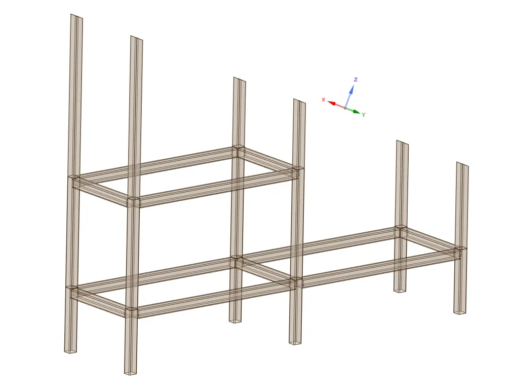
FIGURE 16 : REPRESENTS THE FINAL EXTRACTION OF THE MIDSURFACE.
STEP-16 : The next step after completing midsurface extraction is to check for missing surfaces and make proper connections for the whole model. As mentioned earlier use the missing surface option under repair tool bar to find the missing surface.
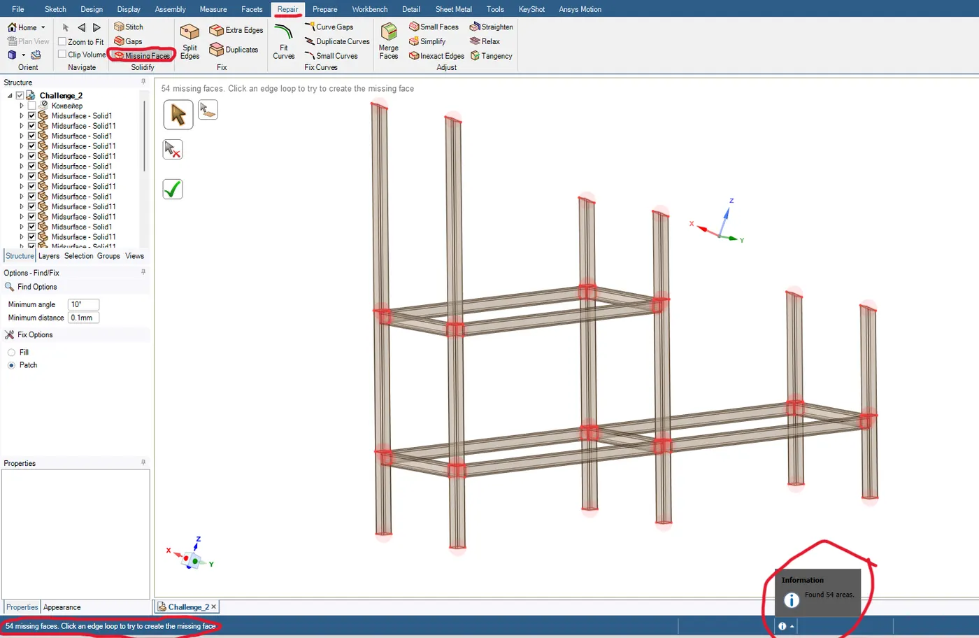
FIGURE 17 : REPRESENTS THE 54 MISSING SURFACE THAT WE NEED TO CONNECT. MISSING SURFACES ARE IN RED.
STEP-17 : Now use the missing surface option to fill the empty surfaces that are the top and bottom surfaces of the vertical tube. Though it is not neccesary to do this step.
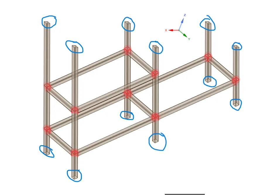
FIGURE 18 : REPRESENTS THE FILLED MISSING SURFACE IN BLUE ROUND MARK.
STEP-18 : Now use the pull option from the design tool bar to extend the missing surface at the intersection parts of the tube.
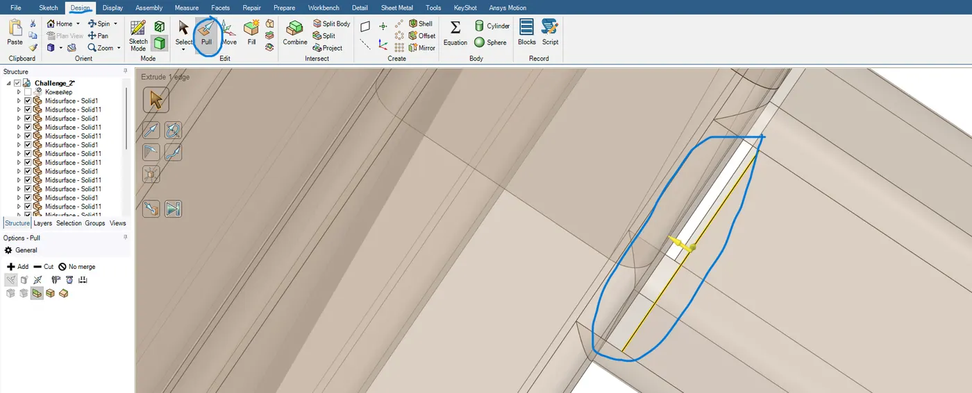
FIGURE 19 : REPRESENTS THE MISSED SURFACE THAT IS BEING FILLED USING THE PULL OPTION UNDER DESIGN TOOLBAR.
STEP-19 : Click the upto surface tool under pull option to fill the surface.
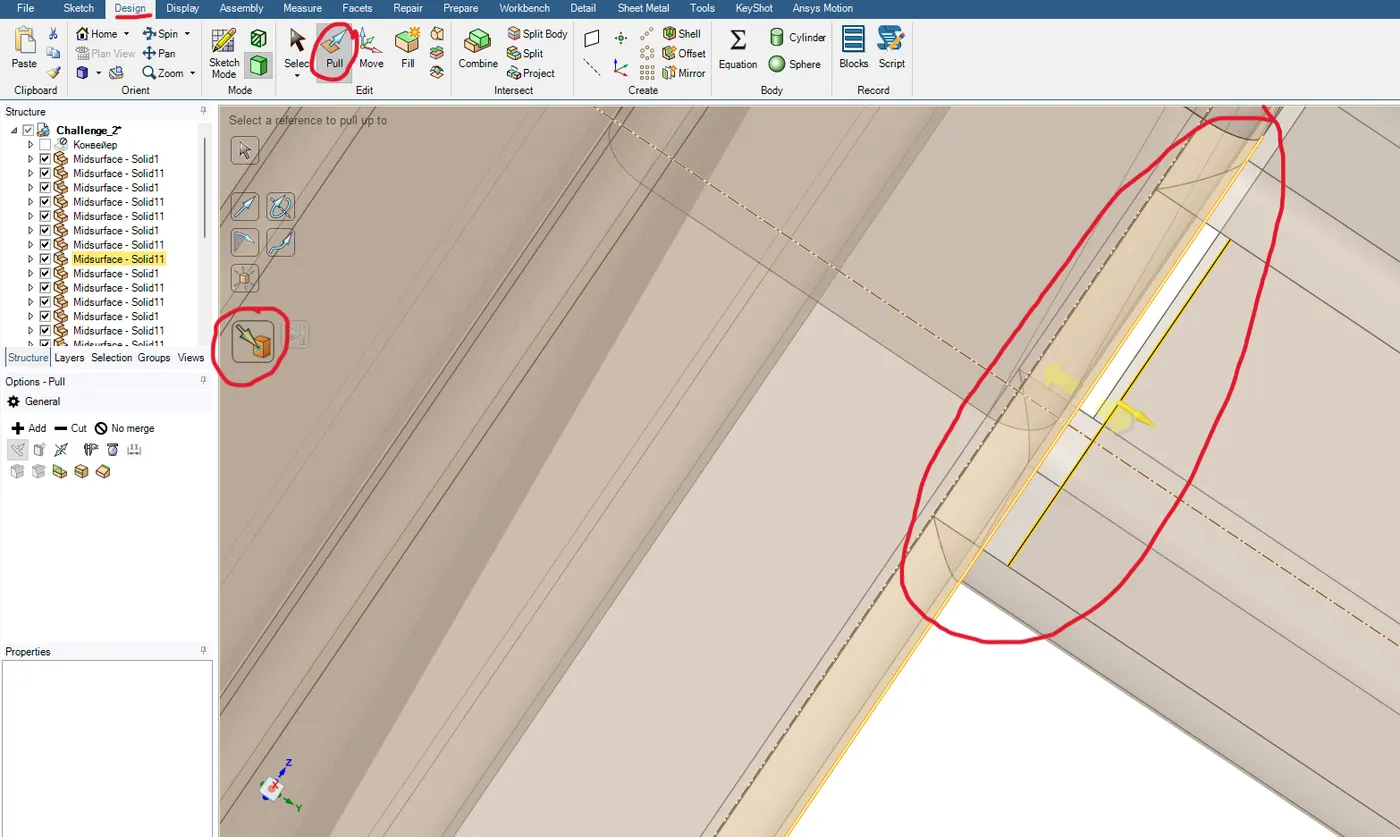
FIGURE 20 : REPRESENTS THE SELECTION OF THE UPTO SURFACE TO FILL THE MISSING FACE.
STEP-20 : Below is the final image of the shared topology using the share option under the workbench tool.
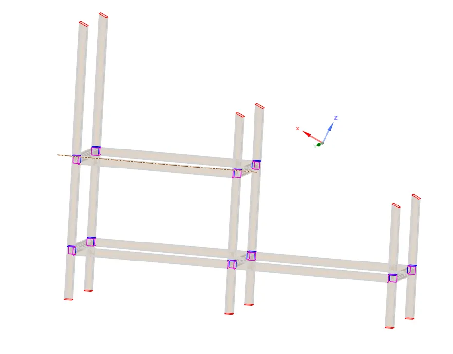
FIGURE 21 : REPRESENTS THE FINAL IMAGE OF THE SHARED TOPOLOGY FOR THE GIVEN TUBE MODEL.
CONCLUSION AND RESULT : Geometry cleanup, midsurface extraction and shared topology has been created for the given tube model.
LEARNING OUTCOME : Through this project i learnt how to apply the concept of geometry cleanup practically and further extracted the midsurface, created a shared topology for the given tube model.
PROJECT 2 : CREATION OF A CAD MODEL AND PERFORMING MODAL ANALYSIS FOR THE CAD MODEL
AIM/OBJECTIVE : To Create a cad model in ansys workbench and perform a modal analysis (free-free run) to verify connections and analyze the results.
PROCEDURE :
STEP-1 : GIVEN CAD MODEL DIMENSION :-
DIMENSION OF BLOCK A - 20(L) * 20(W) * 5(D) [NOTE: ALL DIMENSIONS ARE IN mm]
DIMENSION OF BLOCK B - 40(L) * 40(W) * 10(D) [NOTE: ALL DIMENSIONS ARE IN mm]
NOTE : Block A is kept on Block B
STEP-2 : Create the model using the above dimensions in ansys discovery. Before that open ansys workbench and click on the analysis type i.e., modal analysis under "analysis systems" tool bar located on the left side to the workspace.
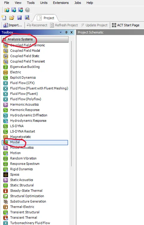
FIGURE 1 : REPRESENTS THE SELECTION OF ANALYSIS TYPE
STEP-3 : After selecting the modal anlsysis a table appears on the workspace representing 7 steps indicating the procedure to solve the fea problem. Any real world engineering problem which needs to be simulated need to be converted into a mathematical model such that the process of simulation becomes easy.
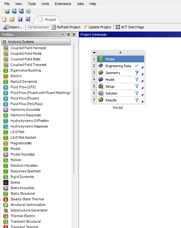
FIGURE 2 : REPRESENTS THE STEPS REQUIRED TO SOLVE THE FEA PROBLEM
STEP-4 : Now right click on the engineering data to assign material and their properties for the modal analysis. Right click on the engineering data and press edit option.
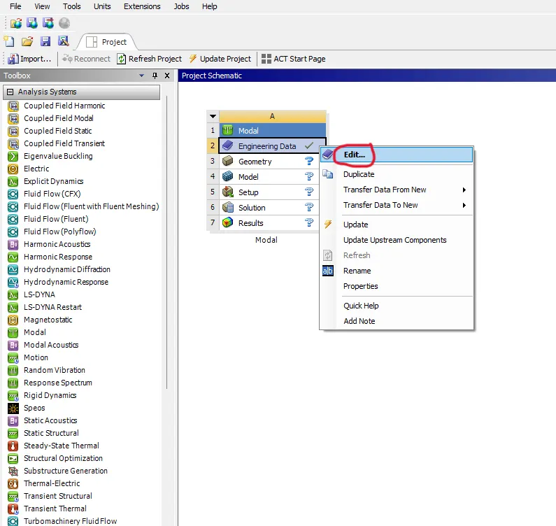
FIGURE 3 : REPRESENTS THE STEPS TO MODIFY THE ENGINEERING DATA.
STEP-5 : A new page or tab appears in which engineering data can be entered. Assign material as structural steel and then enter the values of young's modulus (E) and Poission's ratio (ν).
- VALUE OF MODULUS OF ELASTICITY = 2 X 10^5 MPa.
- VALUE OF POISSION'S RATIO = 0.3
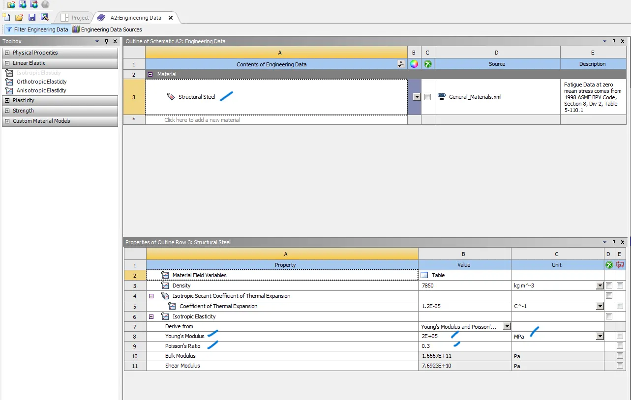
FIGURE 4 : REPRESENTS THE MATERIAL ASSIGNED AND MATERIAL PROPERTIES ENTERED.
STEP-6 : After entering the engineering data close this tab and return back to the main table where we have the steps to solve the problem. Now right click on the geometry step and open new discovery geometry modelling interface to create our CAD model.
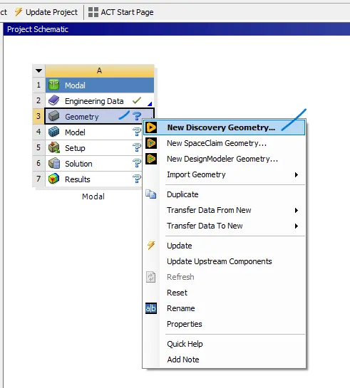
FIGURE 5 : REPRESENTS THE METHOD TO CREATE GEOMETRY IN ANSYS DISCOVERY INTERFACE.
STEP-7 : ANSYS DISCOVERY interface opens and now we can start modelling our CAD model using the sketch option under the design tool bar. Select the rectangle option under teh sketch module. Also for sketching use the top view for convinience whcih is present at the bottom left corner marked in red in the below image.
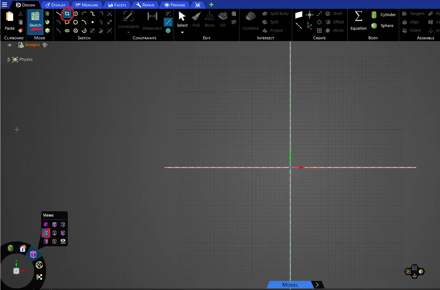
FIGURE 6 : REPRESENTS THE SKETCHING OPTION TO START DESIGNING OUR CAD MODEL.
STEP-8 : Use the pull option to extrude the created sketch by 10mm.
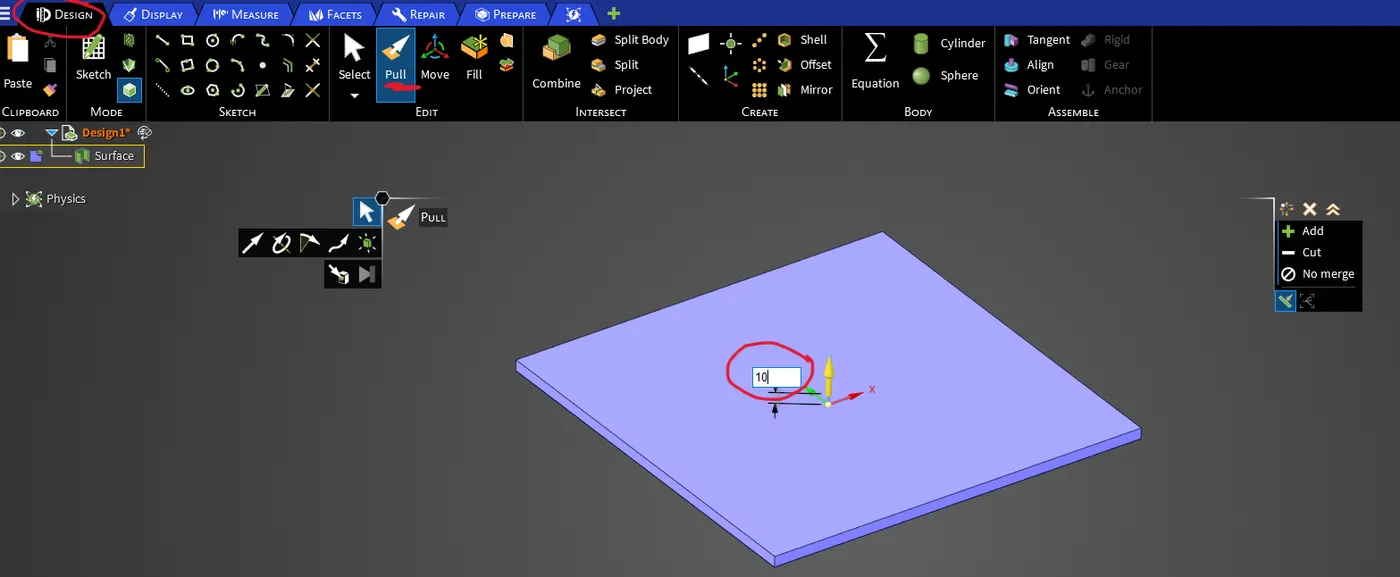
FIGURE 7 : REPRESENTS THE SKETCHING OPTION TO EXTRUDE THE CREATED SKETCH OF BOTTOM "BLOCK B" BY 10mm.
STEP-9 : Now create another block on top of block b that is block A of dimension 20X20X5 (mm) and repeat the same procedure for sketching,then extrude the block by 5mm.Also after creating the design split both the blocks by the option mention in project 1.
NOTE : This time you can use the draw from centre rectangle option to create the sketch in the centre.
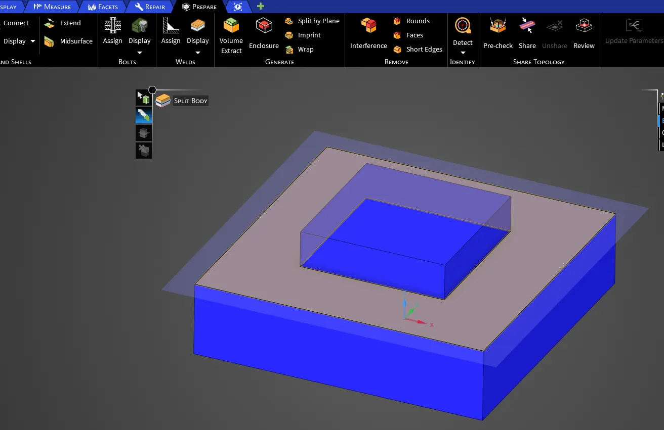
FIGURE 8 : REPRESENTS THE SPLITTING OF THE TWO BLOCKS
STEP-10 : Close and save your model ,then come back to main page and right click on the model option to edit. A new tab ANSYS MECHANICAL opens where the model created in the ANSYS discovery appears at the workspace and first check the material assigned is matching with the data provided in engineering data.
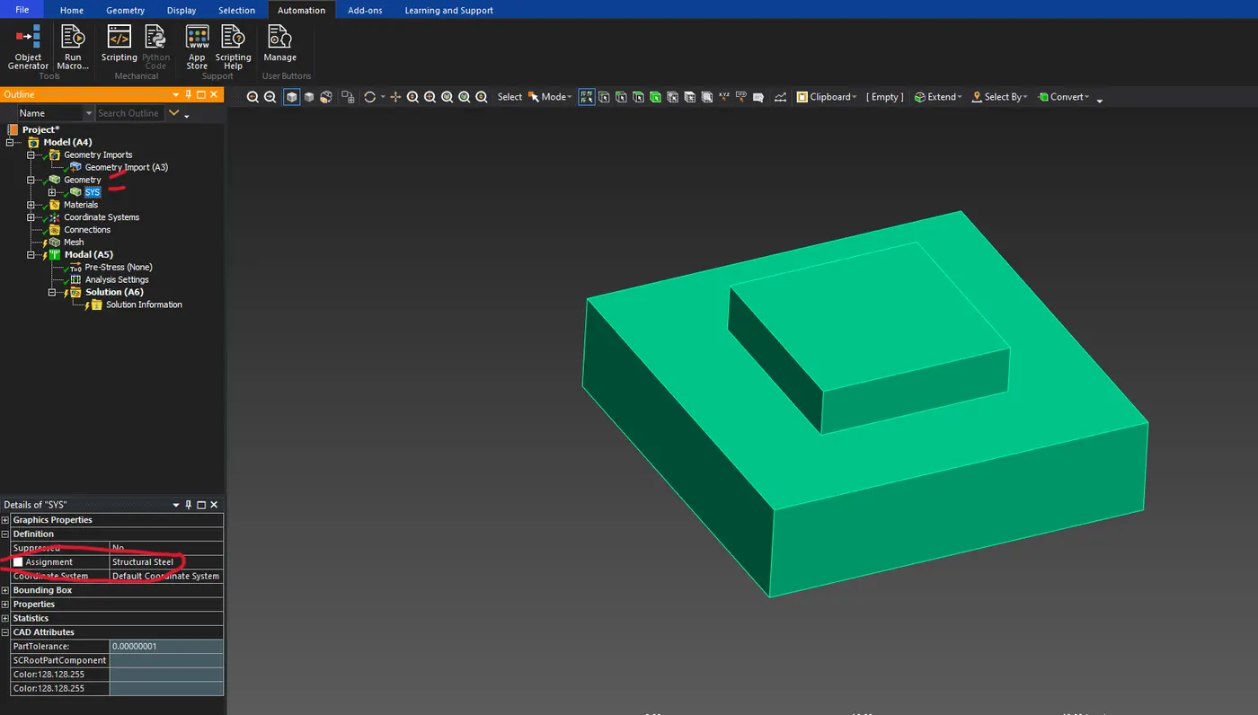
FIGURE 9 : REPRESENTS THE MATERIAL ASSIGNED UNDER THE GEOMETRY OPTION.
STEP-11 : Use the mesh option to choose the mesh method and give it as automatic.You can use the select the body option to cover the geometry. Then right click on the mesh option again to give the element size as 1.5mm.
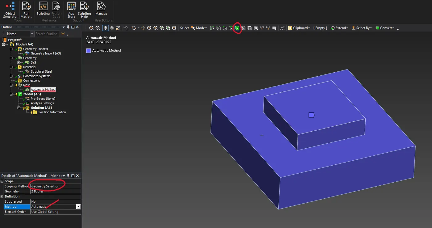
FIGURE 10 : REPRESENTS THE SELECTION OF MESHING METHOD UNDER THE MESH OPTION.
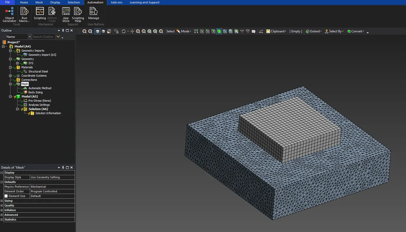
FIGURE 11 : REPRESENTS THE FINAL MESH OF THE CAD MODEL WITH 1mm ELEMENT SIZE.
STEP-12 : In this step we will provide the boundary condition i.e., provide fixed support or the constraint for the Block B. For this go to the modal option and then right click on it and then fix the face of the bottom block B. After fixing the colour of the bottom surface of block B turn to coloured one represting that the face has been fixed.
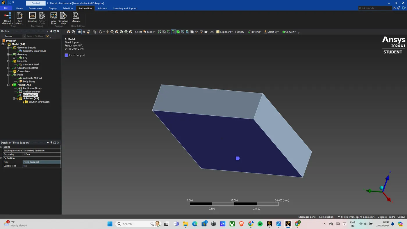
FIGURE 12 : REPRESENTS THE FIXED SUPPORT FOR THE BOTTOM FACE OF BLOCK B.
STEP-13 : To provide connections just check whether the connection is automatic for this case.
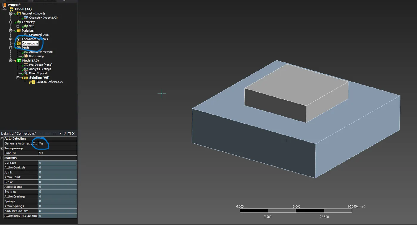
FIGURE 13 : REPRESENTS THE CONNECTION PROVIDED IS AUTOMATIC.
STEP-14 : After setting up the boundary conditions and checking for connections go to analysis settings and set the mode shape to 6.
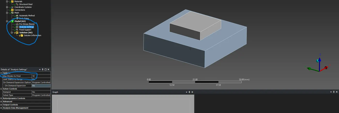
FIGURE 14 : REPRESENTS THE SLECTION OF MAXIMUM NUMBER OF MODE SHAPES TO BE OBTAINED.
STEP-15 : Right click on the solution option and click solve then also click evaluate all results and then finally modes are obtained. Below are the max,min and internediate deformations for the 6 modes.
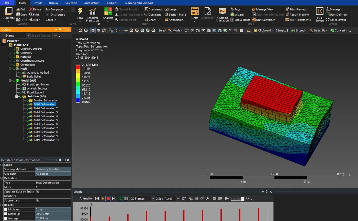
FIGURE 15 : REPRESENT TOTAL DEFROMATION FOR 1ST MODE.
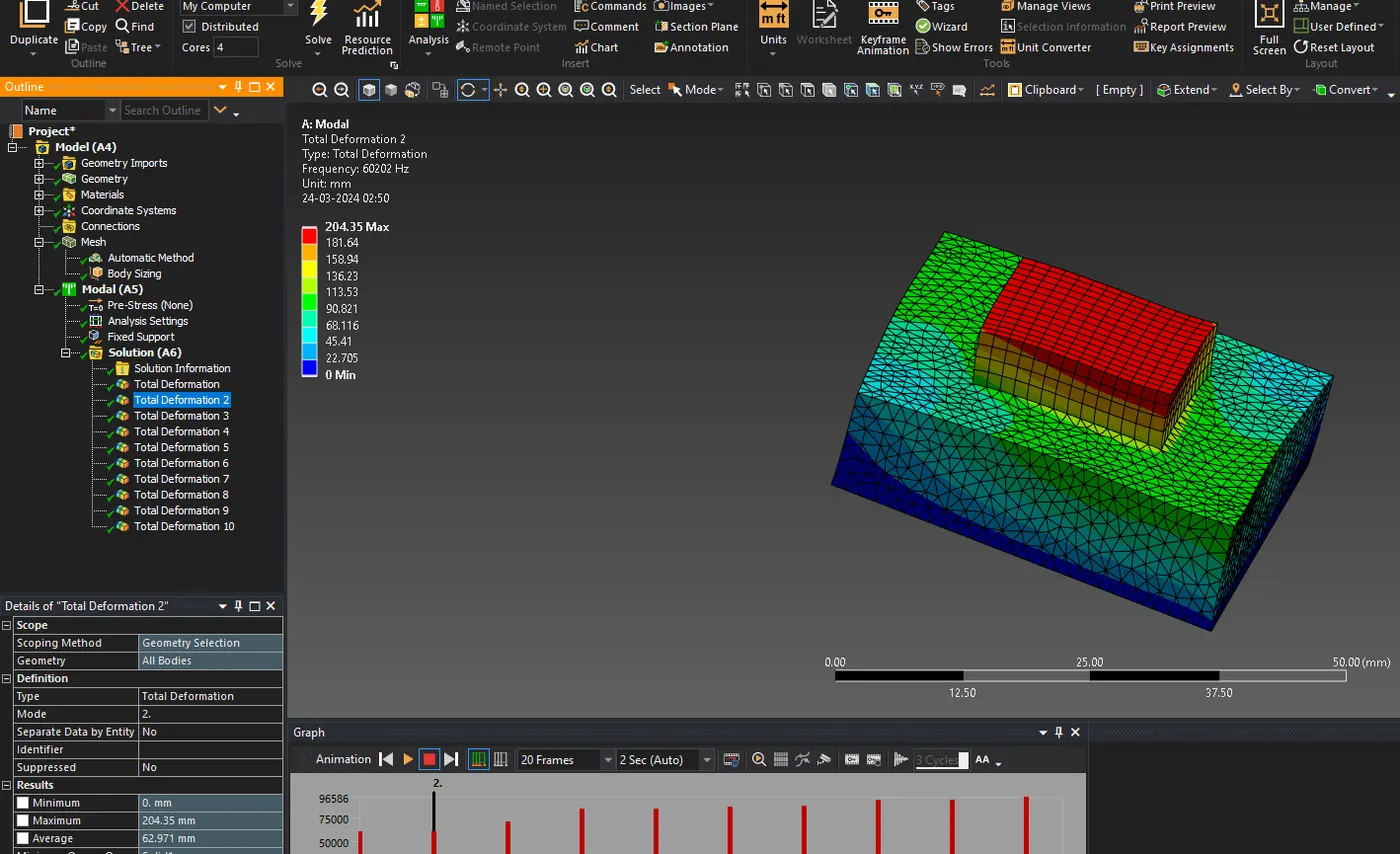
FIGURE 16 : REPRESENT TOTAL DEFROMATION FOR 2ND MODE.
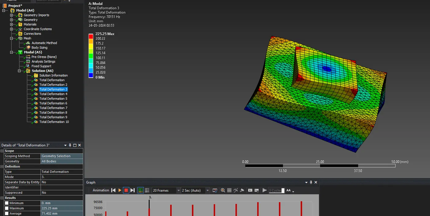
FIGURE 17 : REPRESENT TOTAL DEFROMATION FOR 3RD MODE.
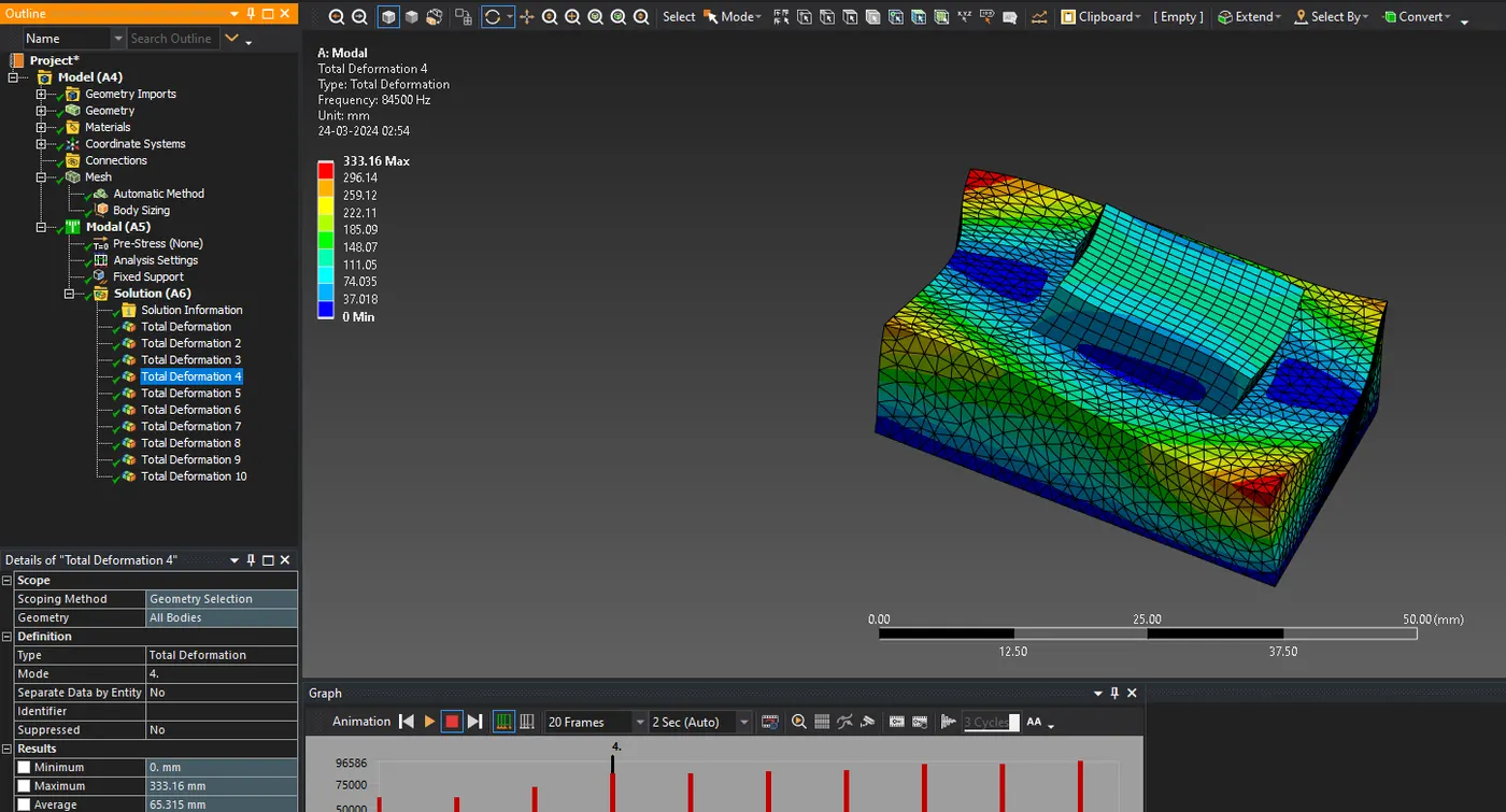
FIGURE 18 : REPRESENT TOTAL DEFROMATION FOR 4TH MODE.
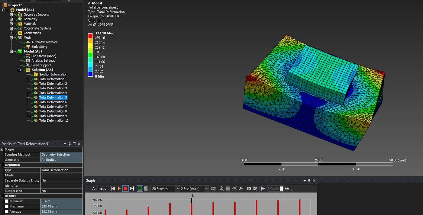
FIGURE 19 : REPRESENT TOTAL DEFROMATION FOR 5TH MODE.
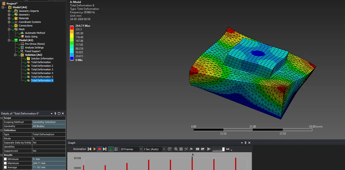
FIGURE 20 : REPRESENT TOTAL DEFROMATION FOR 6TH MODE.
NOTE : THE MAXIMUM, AVERAGE AND MINIMUM VALUE OF THE TOTAL DEFORMATION FOR ALL THE 6 MODE CAN BE SEEN AT THE LEFT SIDE TABLE REPRESENTED AS MIN,MAX,AVERAGE IN ALL THE ABOVE IMAGES FOR 6 MODES.
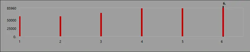
FIGURE 21 : REPRESENTS GRAPH OF NUMBER OF MODES VS FREQUENCY.
: CAD Model is successfully created and shared topology is given. Further analysis and simulation is performed successfully for the created CAD model and the connections are verified.
LEARNING OUTCOME : Through this project i learnt how to create a geometry in ansys discovery. Learnt how to perform a free-free run modal analysis and also learnt to verify the connections.