Week 3: Flow over a backward facing step
JORGE LOZANO
Advanced CFD for IC Engine Applications using Converge
Flow over a backward facing step
Objective
Once you have the base setup ready, run the case for three different base mesh sizes
- dx = dy = dz =2e-3m
- dx = dy = dz =1.5e-3m
- dx = dy = dz =1.0e-3m
Contents to be shown in the report:
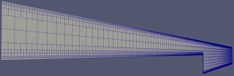
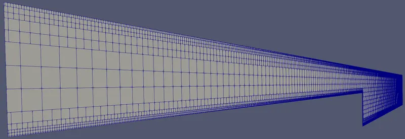
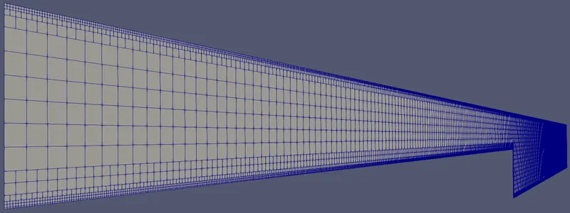
- Show the mesh (i.e surface with edges) for all the 3 base mesh sizes
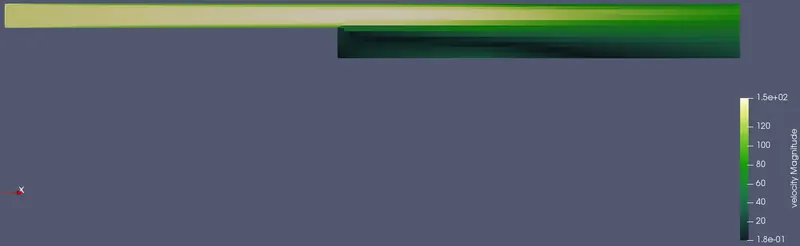
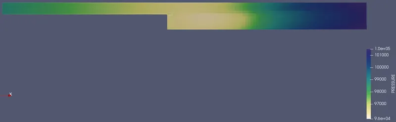
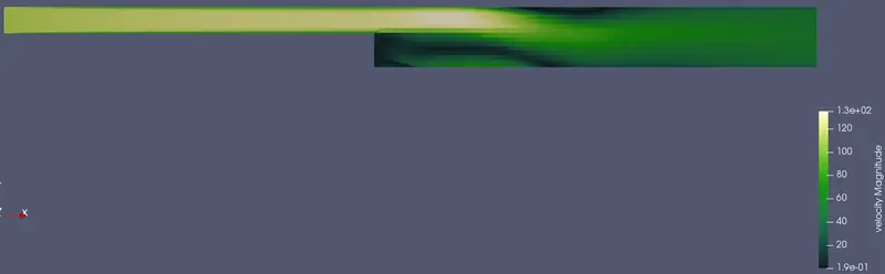
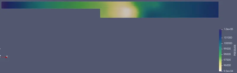
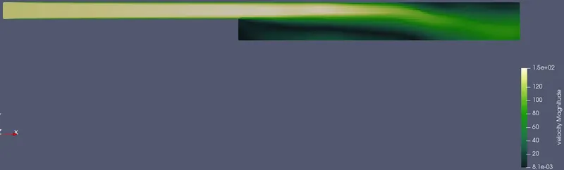
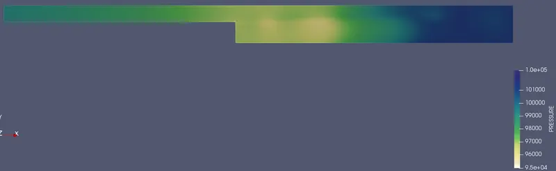
- Show pressure and velocity contours
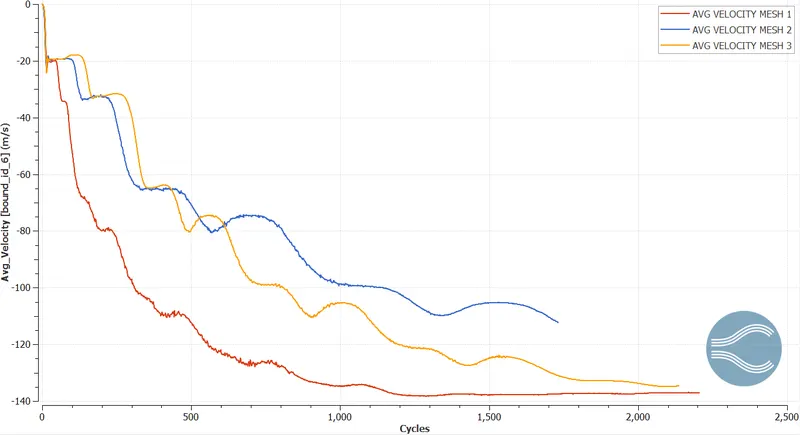
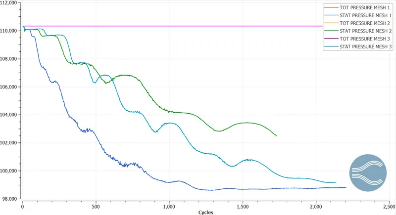
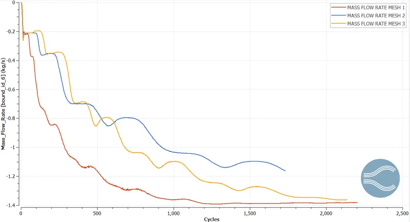
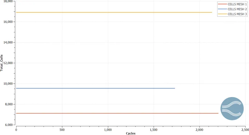
- Show the plots of velocity, pressure, mass flow rate and total cell count for all the 3 base mesh sizes
Pre-processor
Geometry & Case Setup
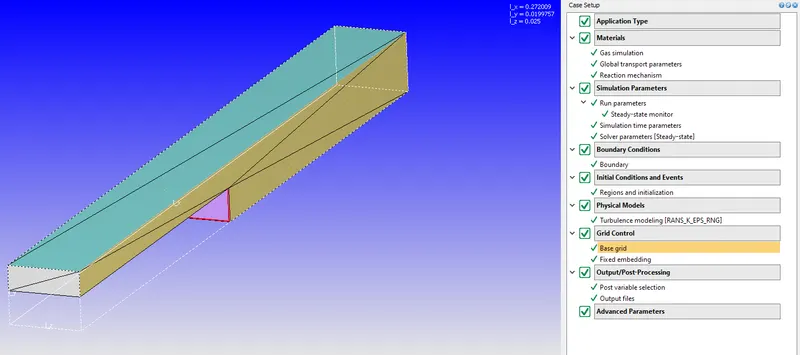
The geometry will be a rectangle with a step as in Fig.1, with the dimensions in meters, but in the boundary conditions there’ll be a 2D boundary selection, omitting the z axis.
The next most important selections will condition the simulation to a certain kind of flow, main material as mixture with oxygen and nitrogen, simulation parameters as what kind of simulation is, how many iterations, algorithm used, initial conditions with the boundaries, grid control, physical models and the post processing variables obtained from the simulation.
The pre-processing was realized in Converge Studio, while the processing of the simulation will be using the software Cygwin which allows systems to be recompiled and run natively on Windows that by using several processors the simulation will be run using the Converge Studio initial conditions.
Postprocessing
CASE 1 [2e-3] Element size
Paraview
Mesh
Velocity contour
Pressure contour
CASE 2 [1.5e-3] Element size
Paraview
Mesh
Velocity contour
Pressure contour
CASE 3 [1e-3] Element size
Paraview
Mesh
Velocity contour
Pressure contour
Converge plots
Velocity plot
Pressure plot
Mass flow rate plot
Cell count
Conclusion
The simulation shows a 2-D simulation by which the results are the velocity and pressure magnitudes, having a turbulent RNG K-E model, applying the law of the wall, and having a pressure difference for the momentum of the flow.
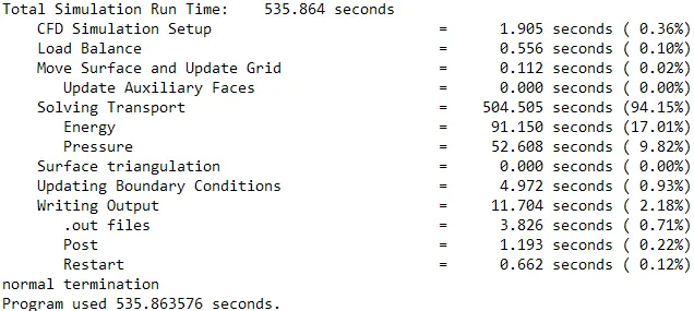
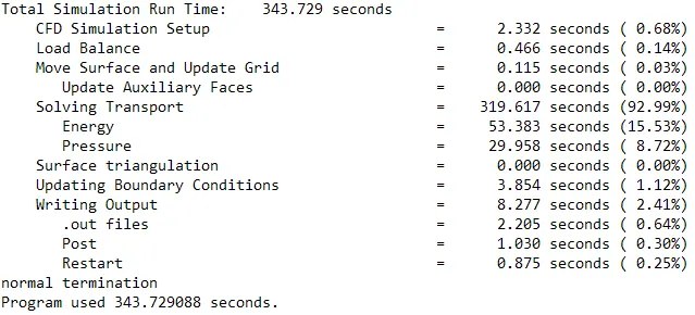
Several mesh element sizes are analyzed to see he effect of the convergence in the outlet boundary of 0.001 having as seen differences of time steps taken and values, which for any of them were finish but due to computational hardware those were the conditions given. Having the scales adaptability of the mesh at the top and bottom of the 2d geometry, with a second level gave the velocity propagation a fine convergence which is offered by converge
As to the reason of the separation or velocity and pressure difference at the step, these are due to the area energy difference in the system before and after the step, having vortices generated and turbulent energy increasing at this area.
Case-1
PRESSURE VIDEO
VELOCITY VIDEO
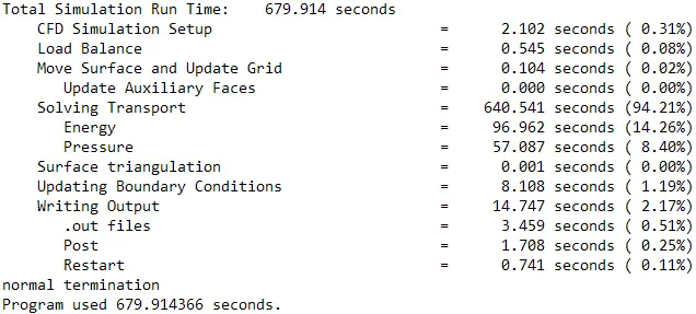
TIME ANALYSIS
Case-2
PRESSURE VIDEO
VELOCITY VIDEO
TIME ANALYSIS
Case-3
PRESSURE VIDEO
VELOCITY VIDEO
TIME ANALYSIS
Reference