Week 3 - External flow simulation over an Ahmed body.
AIM
To simulate external flow over an Ahmed body using ANSYS software.
The simulation is run for the velocity of 25m/s with the default air properties in ANSYS Fluent software.
INTORDUCTION
Aerodynamics of an automobile body is a crucial part in the designing process. Reducing the aerodynamics factors like drag & lift is more efficient than increasing the power of the vehicle or decreasing the weight of the vehicle. And for this purpose a good model of automobile body is required on which accurate flow simulations can be carried out and the aerodynamic properties can be measured. Ahmed body is such a reference model chosen as the benchmark for carrying out computations for studying the aerodynamic properties.
GOVERNING EQUATIONS
To calculate the first layer thickness following equations are needed.
- Reynolds number , `Re = (UD)/nu`
Where , `U` is the flow velocity , `D` is the hydraulic diameter and `nu` is the kinematic viscosity of the fluid.
- Hydraulic diameter , `D = (4A_c)/p`
Where , `A_c` is the cross-sectional area and `p` is the perimeter.
- Skin friction coefficient, `C_f = 0.0576*Re^(-1/5)`
- Wall shear stress, `tau_w = 1/2*C_f *rho*U^2`
Where , `rho` is the density of the fluid.
- Frictional velocity , `U_t = sqrt(tau_w/rho)`
- First layer thickness , `y =(y^+*nu)/U_t`
Where , `y^+` is the dimensionless wall distance.
OBJECTIVE
- To plot and analyze velocity and pressure contours.
- To calculate the drag coefficient.
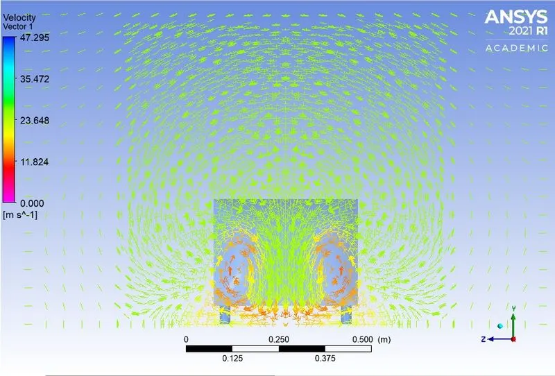
- Wake region visualization using vector plots.
- To perform grid independence test and to provide the values of drag & lift for each case.
THEORY
An Ahmed body is a reference model used for aerodynamics analysis of automobile bodies. The importance of Ahmed body is that it is a simplified geometry representing the automobile body and hence easier to perform the simulations. This body is made up of a round front part , a movable slant plane in the rear and a rectangular box which connects the front and the rear parts. Even though the Ahmed body is a simplified model of a automobile body it still have all the flow feature that a actual moving car has.
The standard geometry and dimensions of an Ahmed body is shown below,
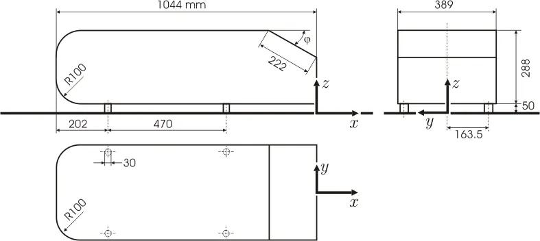
The rear slant angle `psi` can be varied to study its effect on the formation of the wake region. Here wake is the region of re-circulating flow immediately behind a moving or stationary solid body, caused by the flow of surrounding fluid around the body.
PROCEDURE
- To set up the geometry space claim software is used. The 3-D geometry created using this software is shown below ,
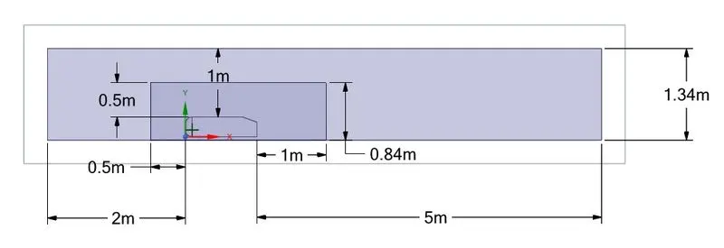
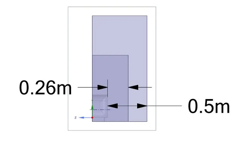
- The enclosure tool has been used to create the box around the Ahmed body. And then the split body tool is used to cut the geometry into half along the x-axis.
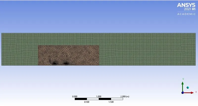
- To mesh this geometry ANSYS meshing software is used. The method used to mesh the outer enclosure is multizone and for the inner enclosure body sizing is done to refine that part only.
- For the leg of the Ahmed body , face sizing is done to create smooth circle.
- An inflation layer is created around the Ahmed body geometry. The properties are shown below. The first layer thickness is calculated for `y^+` value of 30 as the simulation is done for turbulent layer.
- Then the inlet,outlet, car wall and symmetry boundaries are named for this geometry.
Grid independence test
The inner enclosure is refined to test for grid independence. Three different element sizes are used for this.
- First case:- Outer enclosure element size = 50mm
Inner enclosure element size = 50mm
- Second case:- Outer enclosure element size = 50mm
Inner enclosure element size = 40mm
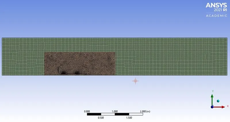
- Third case:- Outer enclosure element size = 50mm
Inner enclosure element size = 30mm
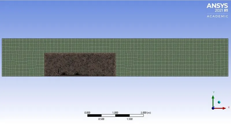
Now the simulation is carried out for all three mesh sizes and the corresponding values of drag coefficient and lift coefficient are calculated. For this we need to set-up the simulation parameters in ANSYS Fluent.
SIMULATION SET-UP
- Solution scheme used is Coupled pressure-velocity coupling.
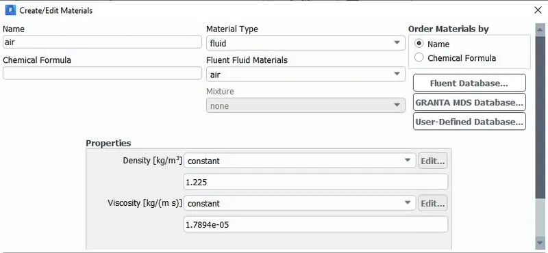
- Material used for the fluid is default air.
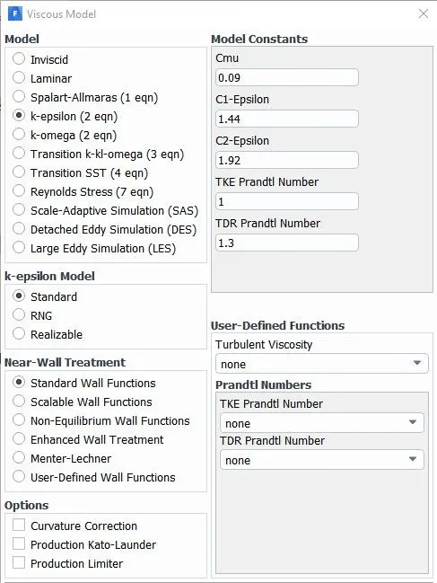
- Turbulence model used is standard k-epsilon with standard wall functions.
- Boundary conditions are specified with inlet velocity as 25m/s and pressure as 1atm.
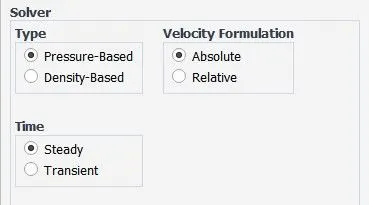
- Pressure based steady state solver is used.
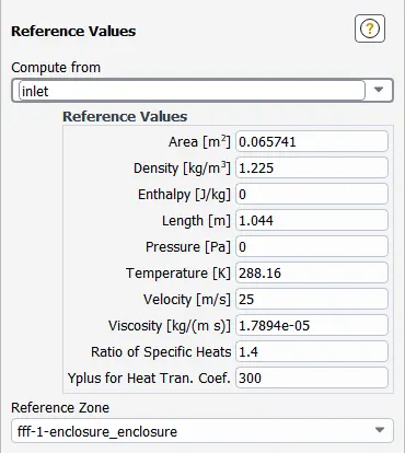
- To calculate the drag coefficient and lift coefficient the reference values has to be provided as shown below,
- Then under definitions a force report has to be created for drag coefficient (`C_d`) and lift coefficient (`C_L`) separately. This will give us the required values and plots.
- After setting up , the simulations for grid independence test is done and the values from these simulations are shown in the table given below,
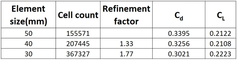
- The refined mesh will be used for further analysis.
RESULTS
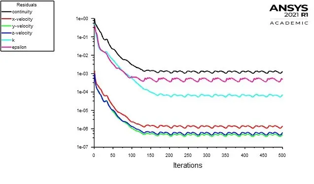
- Convergence plot
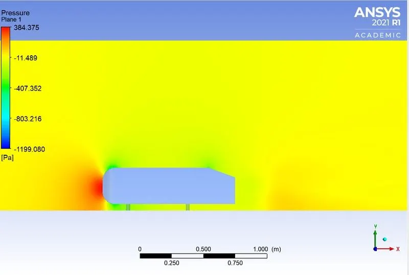
- Pressure variations
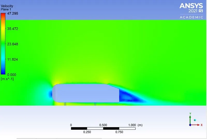
- Velocity variations
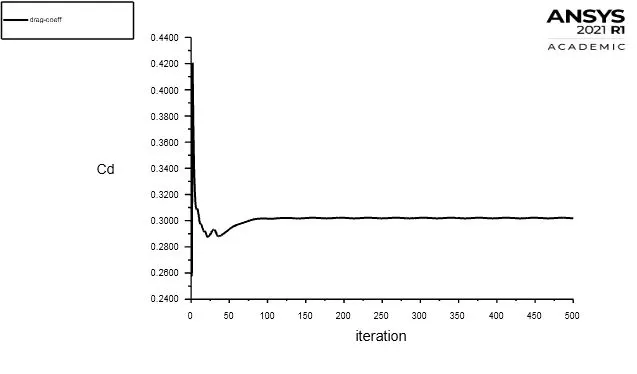
- Drag coefficient plot
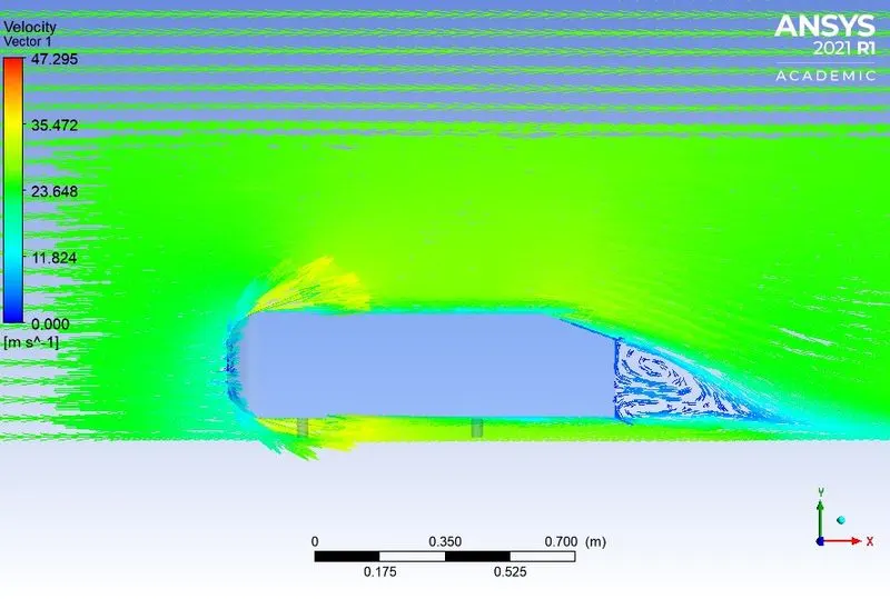
- Velocity vector plot showing the wake region
CONCLUSION
The simulation of external flow over an Ahmed body has been done successfully using ANSYS software.
The wake region has been visualized using the velocity vector plots. Also the coefficient of drag and lift values at flow velocity 25m/s has been calculated.
From the pressure variations diagram it can be concluded that the maximum pressure acts at the frontal area of the Ahmed body. As the airflow moves towards the rear of the body the pressure drops and creates low pressure region. This low pressure region causes lift which acts on the rear part of the body.
The separation layer causes the pressure to be negative at the wake region. This is caused due to the slant in the rear part of the body , where the air flow gets separated and creates a notch. This will form a vacuum or very low pressure space.
The point of separation determines the size of the separation zone which affects the drag force. Hence the point of separation is crucial in determining the accurate drag force values.
The calculated values of Coefficient of drag and coefficient of lift are 0.302 and 0.222 respectively.
REFERENCE
- Lienhart , C. Stoots , S. Becker , Flow and Turbulence Structures in the Wake of a Simplified Car Model (Ahmed model).
- Meile, G. Brenn, A. Reppenhagen, B. Lechner, A. Fuchs ,Experiments and numerical simulations on the aerodynamics of the Ahmed body , Vol. 3 (1) – March 2011.