Week 3 - External flow simulation over an Ahmed body.
1. Here we started with Ahmed body and its temperature,
*Ahmed body is a simplified car model that is used to study the flow of air around a car and to design new car models.
Ahmed body is important because:
* It helps to understood the turbulent flow around a car-like geometry.
* It is baseline geometry for automobiles industry.
* It helps to validate numerical models used in vehicle aerodynamics.
* It helps to design new car models.
2. Reason for the negative pressure in the wake region:
* Negative pressure in the wake region is caused by flow separation, which can occur when the velocity gradient become zero, This can happen when air moves over a vehicle or a cylinder. when air separates at the rear of a vehicle, It creates a large low pressure area behind the vehicle, Known as the wake. This wake contributes to pressure drag, which can reduce the vehicle's performance.
The pressure inside the wake region remains low as the flow separates and a net pressure force (pressure drag) is produced. In the words, Due to the production of pressure drag being produced from flow separation. The pressure in the wake region is low.
3. The significance of the point of separation:
The point of separation of an Ahmed body is important because it's where the flow of air separates from the body crates vortices and negative pressure in the wake region, which can negatively affect drag.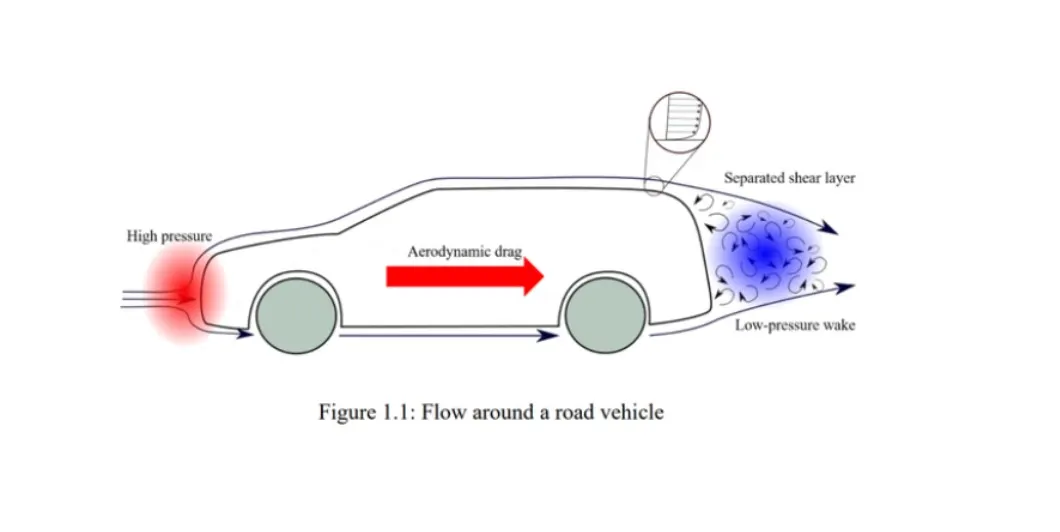
Case:1
First we started with geometry setup:
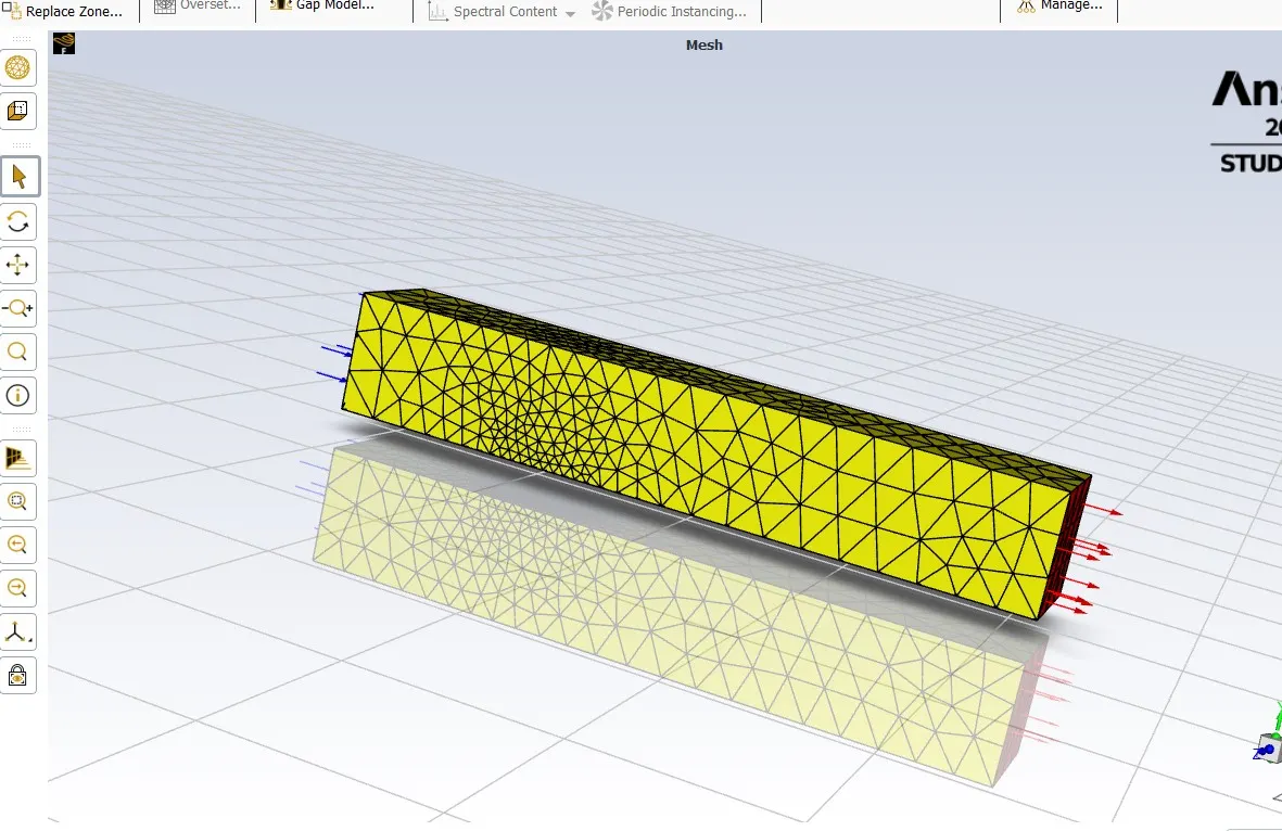
The Ahmed body is a 3D model for a basic car simulation. For this project we're going to create enclosure for given model and cut the model along z axis for the reduction of cells in mesh.
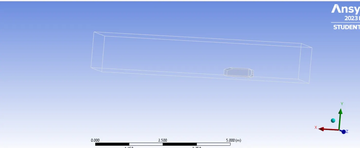
The outer enclosure is 5m towards rear end of the Ahmed body and front side is 2m.
The base of the Ahmed body is 0m.
The top of the Ahmed body is 1m.
The width will be 0.5m for both sides.
After that we closed it and we gone for meshing interface then we started with normal base meshing method.
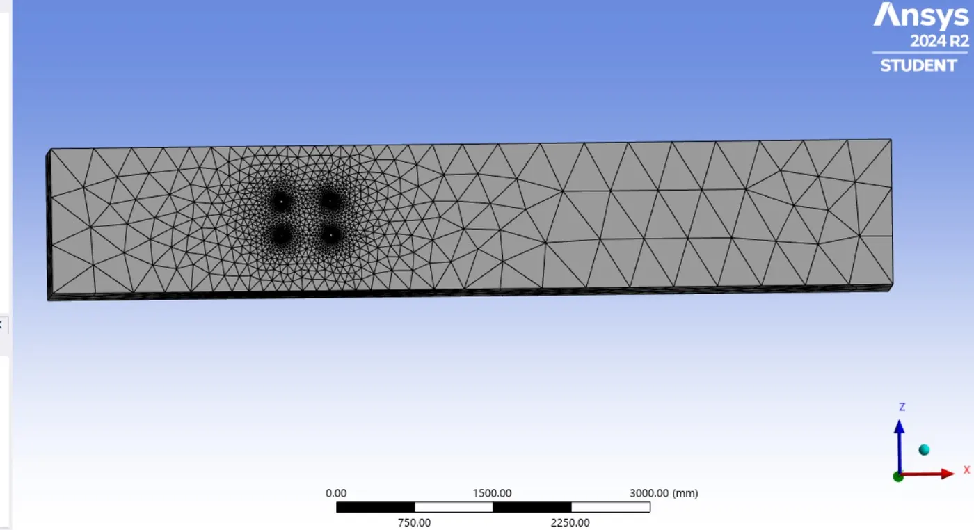
After that we did section of the body.
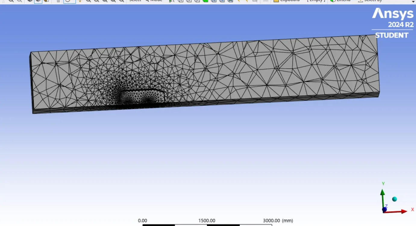
The enclosure part is meshed using multizone mesh method to get accurate results based on the shape of the enclosure and it fit's tetrahedral mesh and normal mesh wherever it needed in the model. Then after that we started for named selection.
Inlet
Outlet
Symmetry wall
Car wall
The mesh also carried by using named selection option in stead of geometry. After we started the setup then the solver pressure based type and the velocity are absolute.
Slover type Pressure based
Velocity Formulation Absolute
Time Steady State
Viscous Model K -Epsilon
Area 0.1115032m^2
Length 1.044m
Pressure 0pascal
Method Hybrid Simulation
Inlet Velocity 25m/s
Material Fluid-air
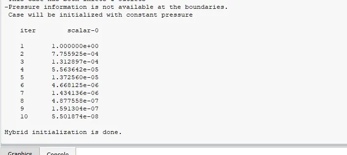
We did initialization so we got after 10 iteration the hybrid initialization is done, then the simulation run up to 1500 iteration for each and every case setup.
Case:1
Results:-
Residual Plot:-
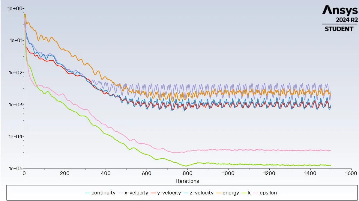
Here we can see after 800 iteration the solution is converged.
Drag coefficient:-
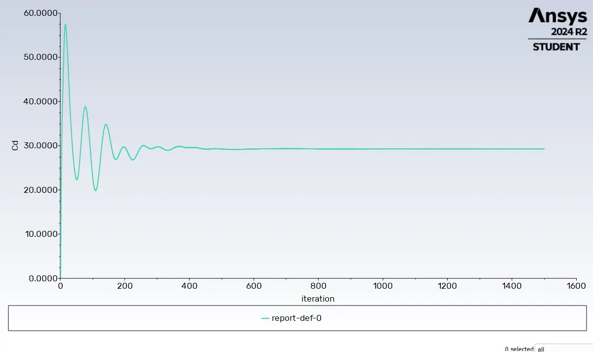
Cd=0.32598367
Lift Coefficient:-
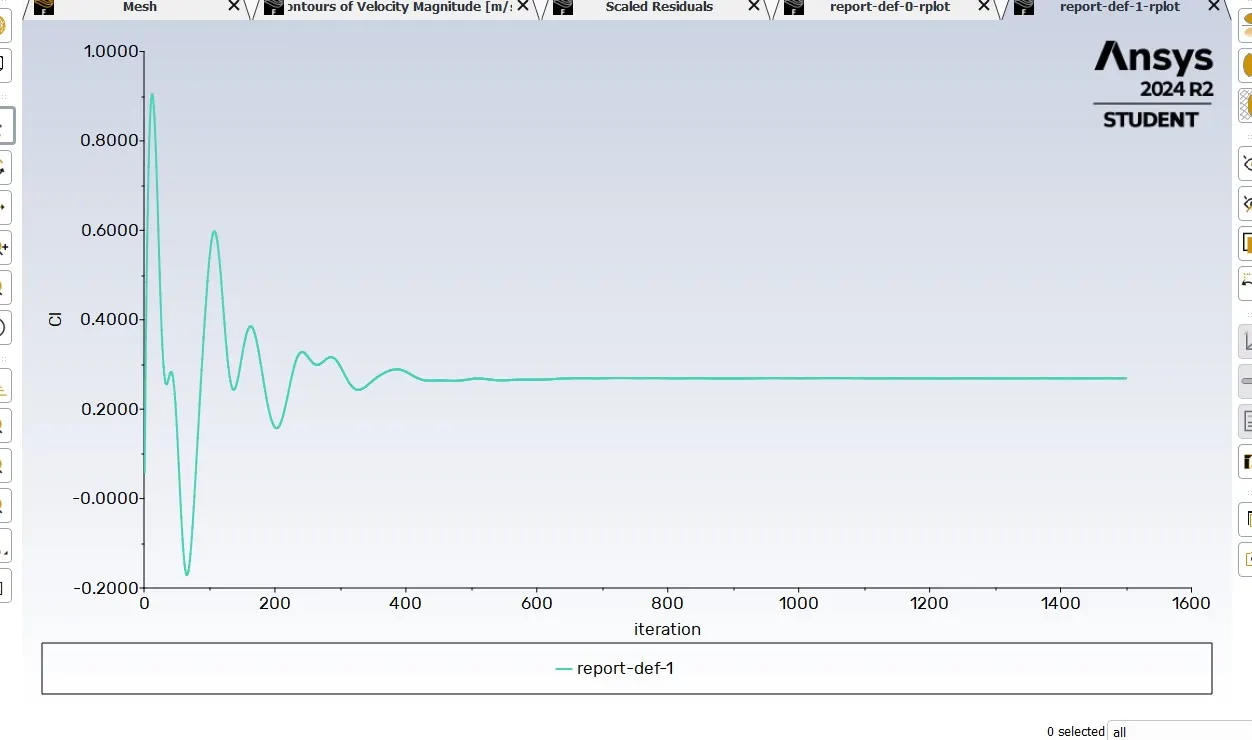
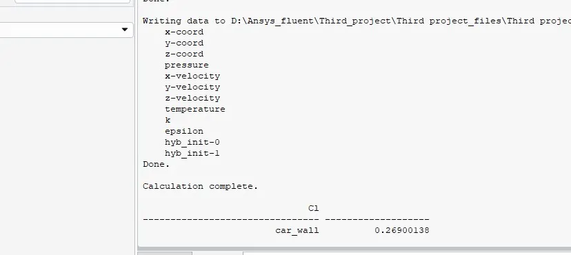
CI=0.26900138
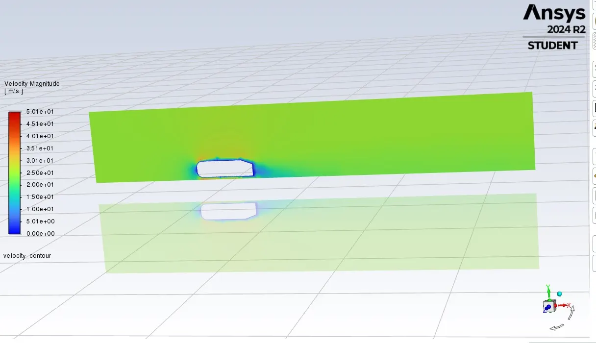
Velocity Contour plot:-
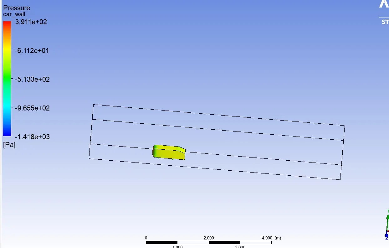
Pressure on car wall:-
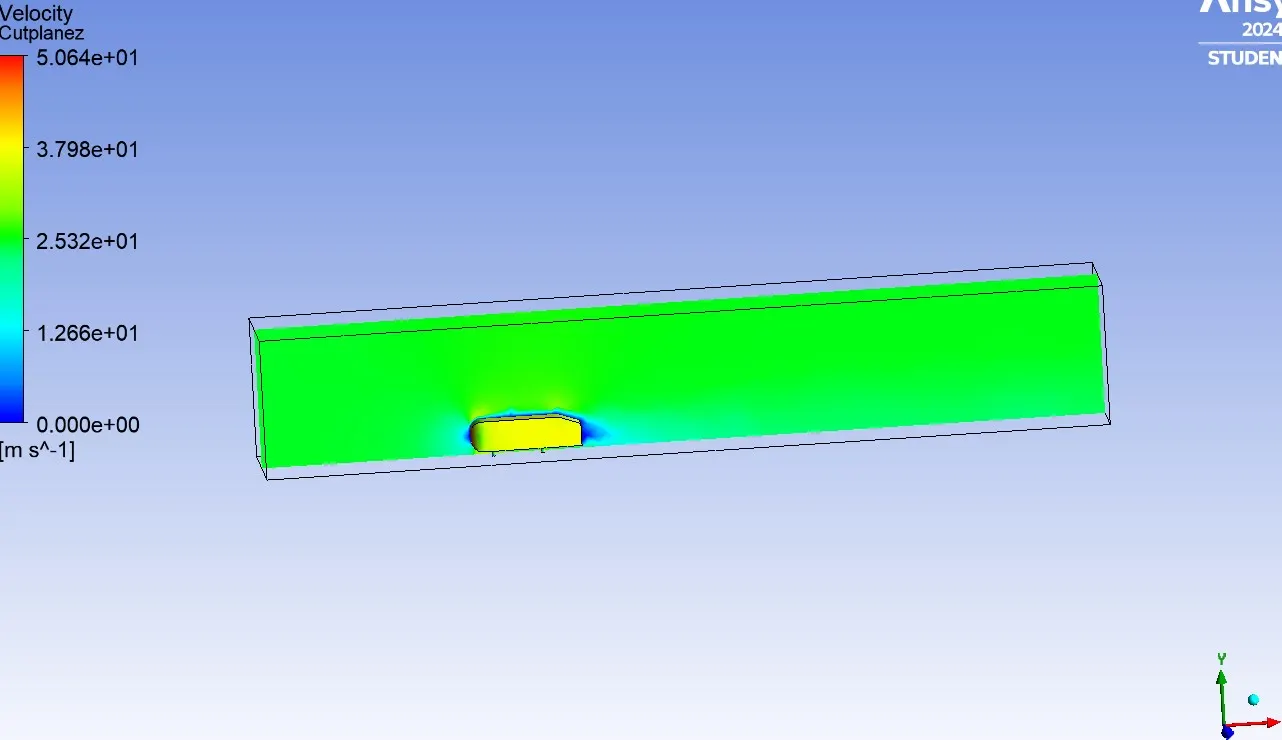
Velocity Contour cut plane Z:-
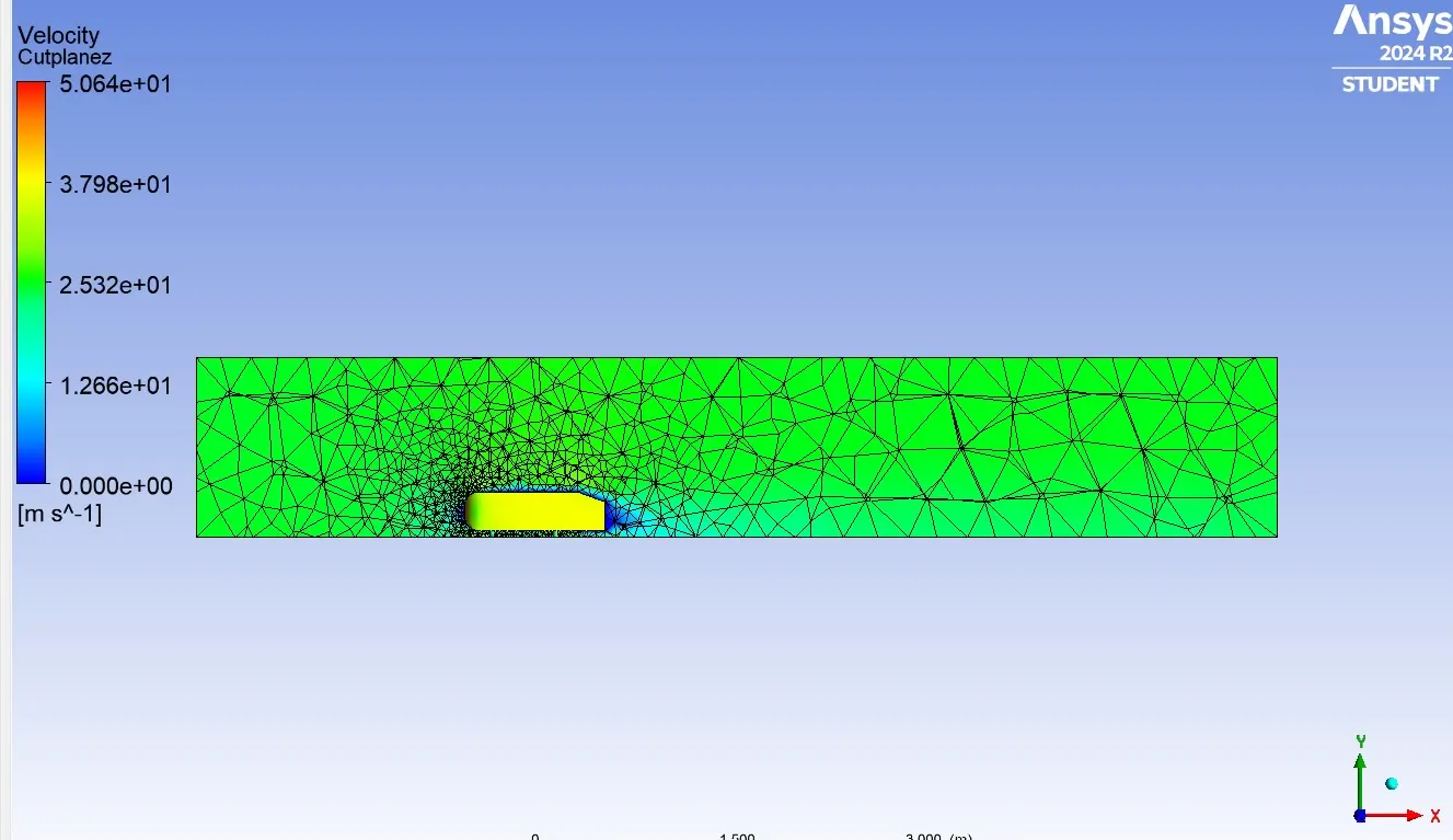
Velocity Contour cut plane Z with meshing:-
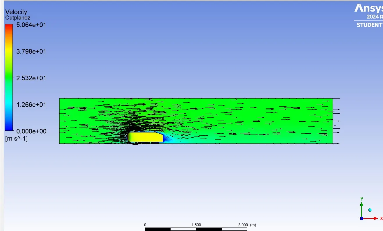
Vector plot:-
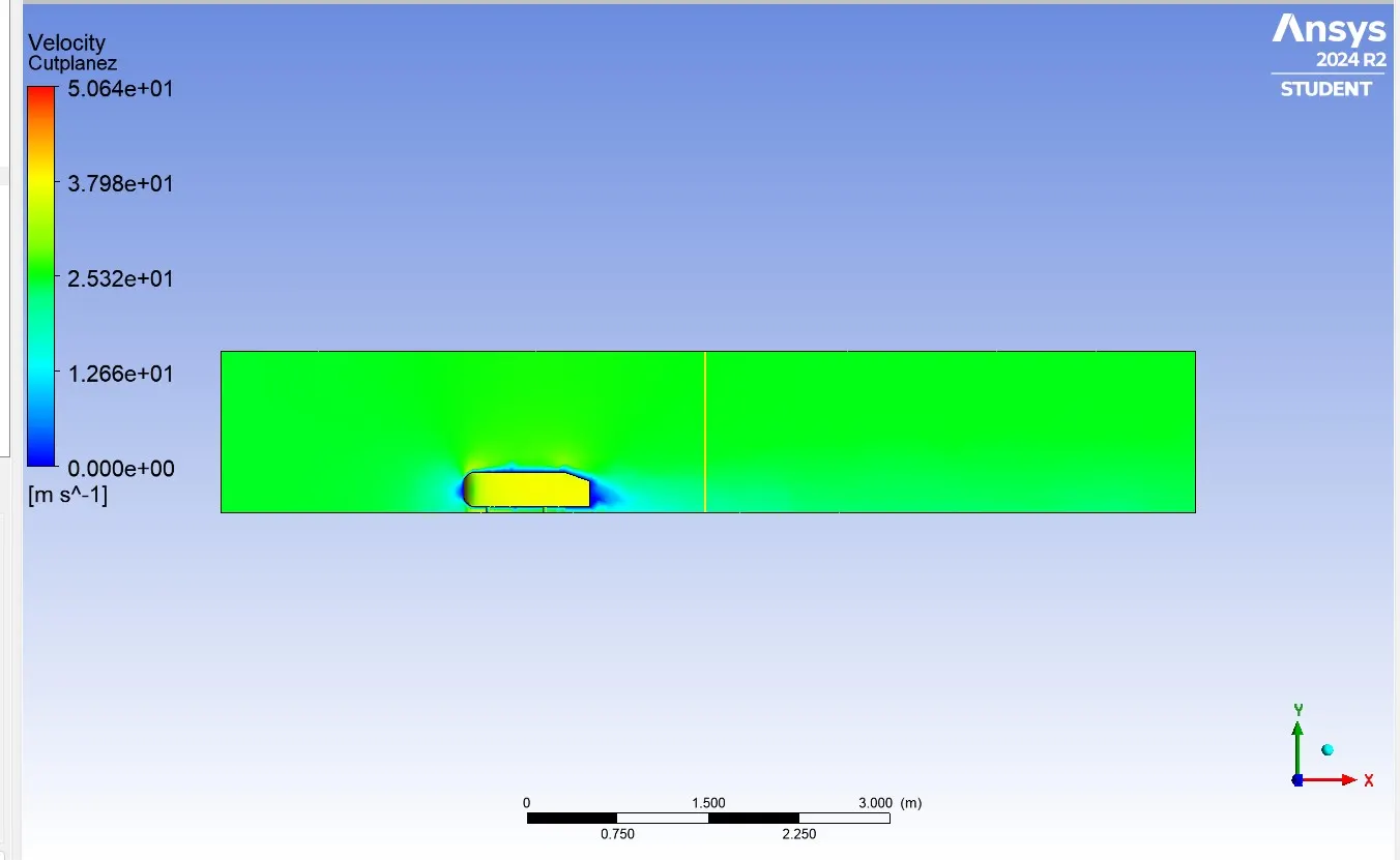
Line 1:-
Line 2:-
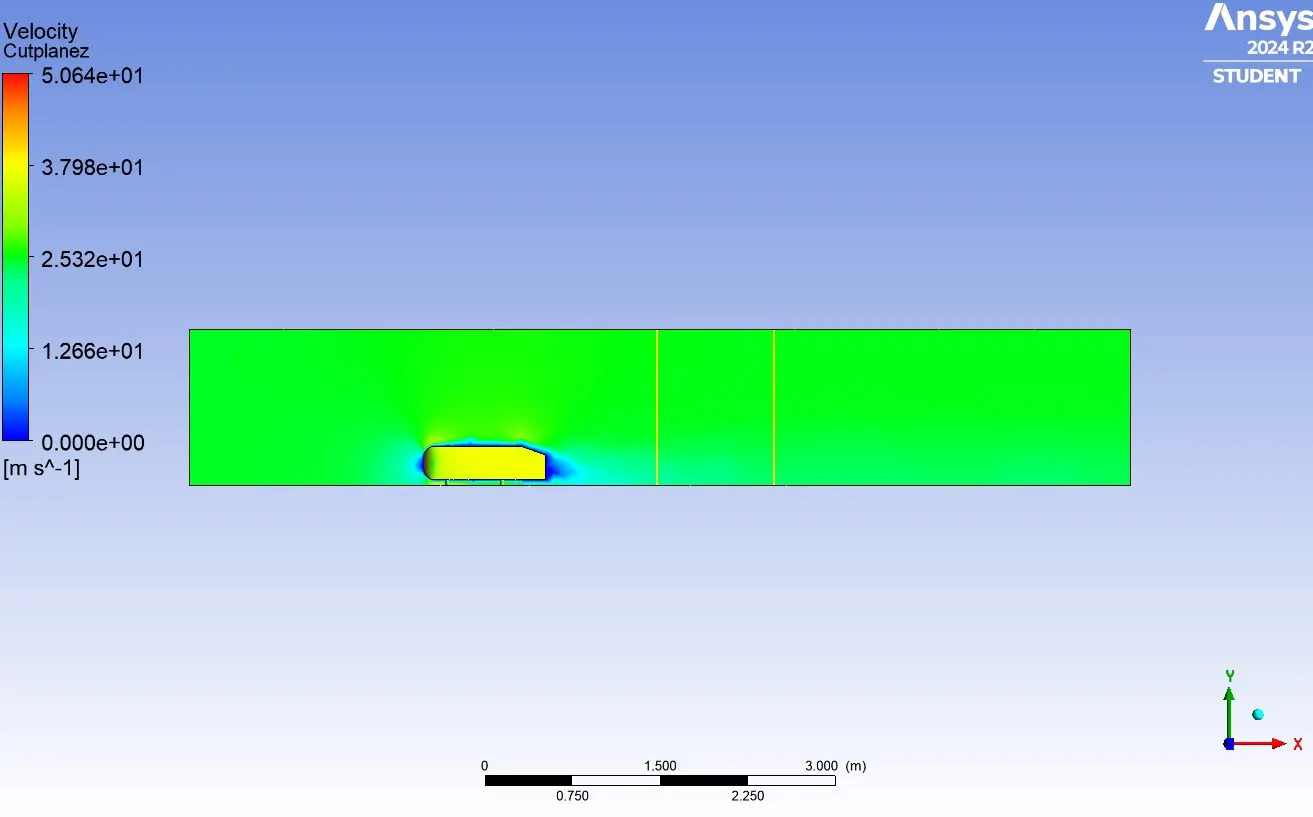
Chart line 1:-
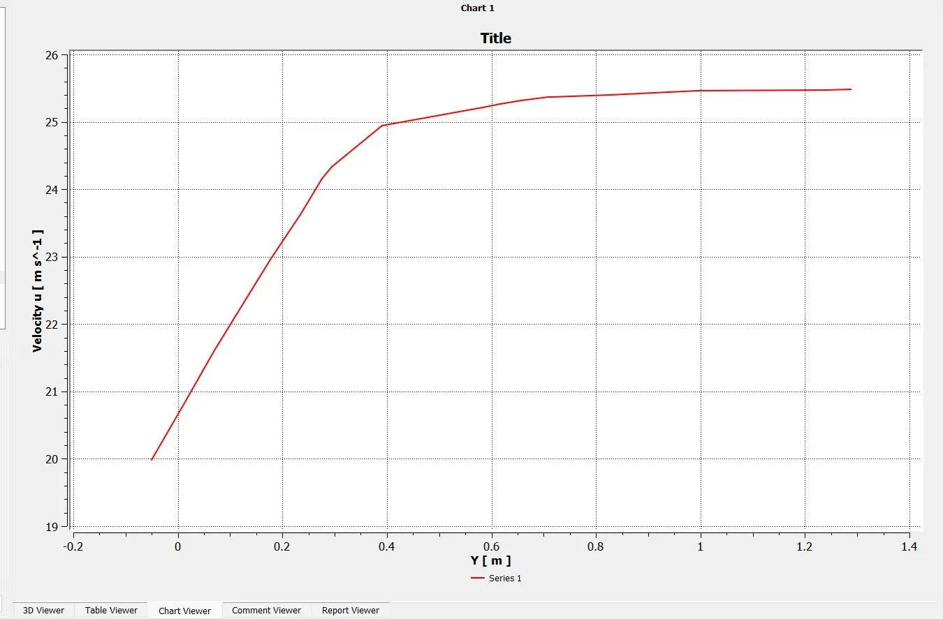
Chart line 2:-
Case-2:-
Inner enclosers for the model:-
The outer enclosure is 1m towards rear end of the Ahmed body front side is 0.5m.
The base of the Ahmed body is 0m.
The top of the Ahmed body is 0.5.
The width will be 0.5m for both sides.
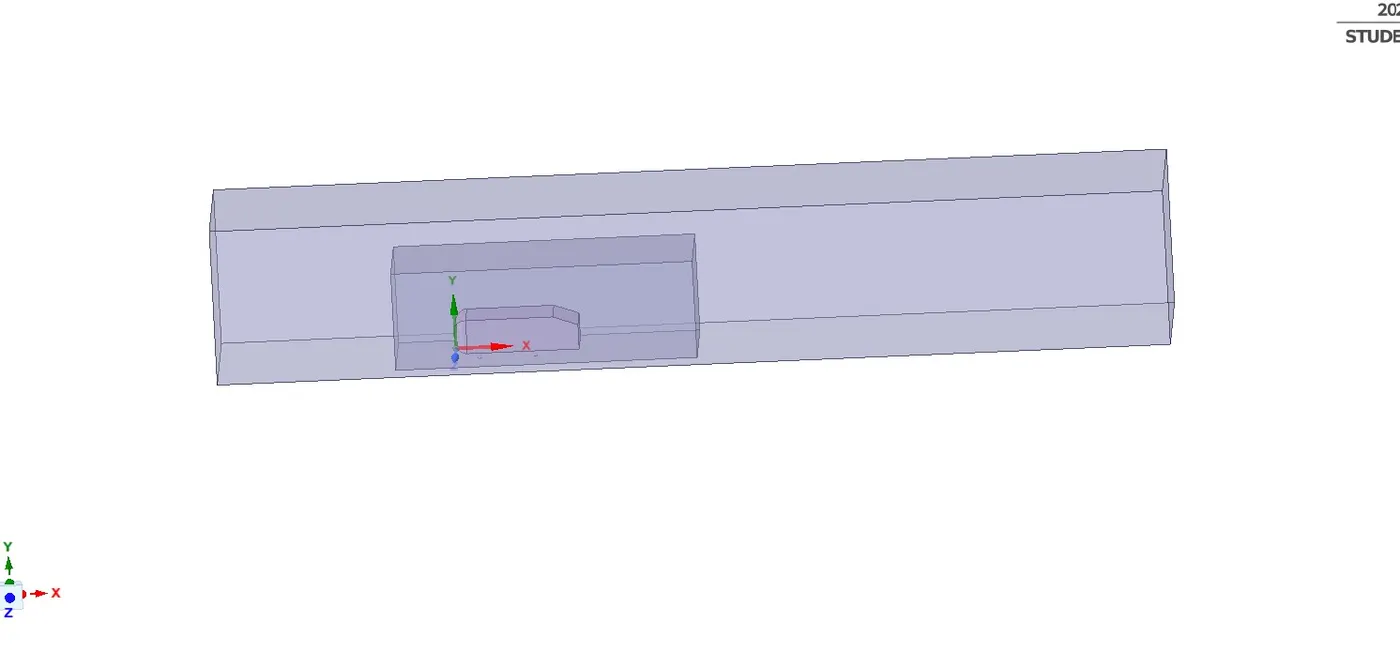
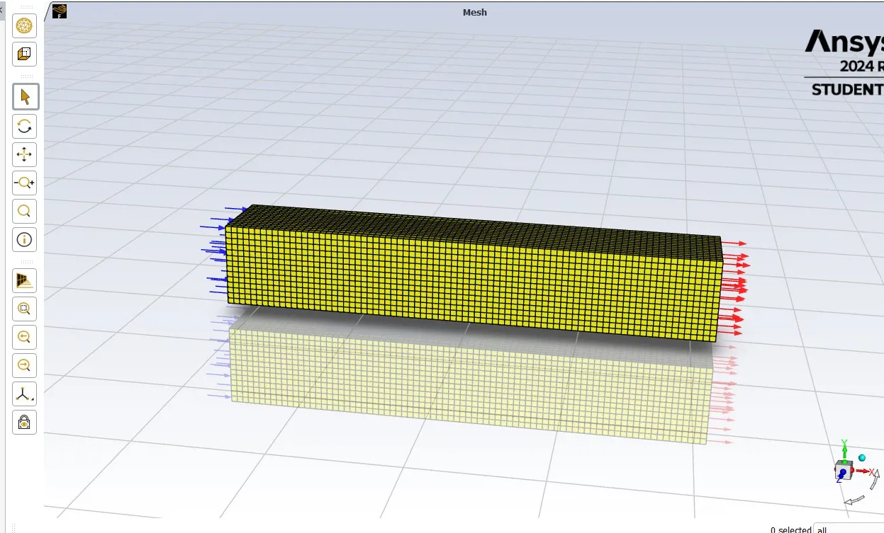
In the above image we've created two enclosures for the Ahmed body, inner & outer enclosures.
After that we closed it and then we gone for meshing interface then we started with normal base meshing method.
The outer enclosure part is meshed using multizone mesh method to get accurate results based on the shape of the enclosure and it fits tetrahedral mesh and normal mesh wherever it needed in the model. The inner enclosure is meshed with default mesh.
For outer enclosure=100 mm(multizone)
Inner enclosure=50 mm (default mesh)
No of inflation layers=6, with first layer thickness using Y+ of 50.
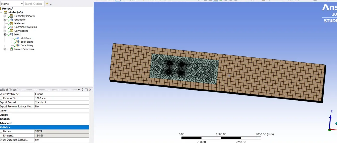
After that we did section of the body, Then we started the named selection.
Inlet
Outlet
Symmetry wall
Car wall
The mesh also carried by using named selection option in stead of geometry. After we started the setup then the solver is pressure based type and velocity are absolute.
Slover type Pressure based
Velocity Formulation Absolute
Time Steady state
Viscous Model K-Epsilon
Area 0.131482m^2
Length 1.044m
Density 1.225kg/m^3
Dynamic viscosity 1.7894e-05kg/ms
Pressure 0pascal
Method Hybrid Simulation
Inlet Velocity 25m/s
Material Fluid-air
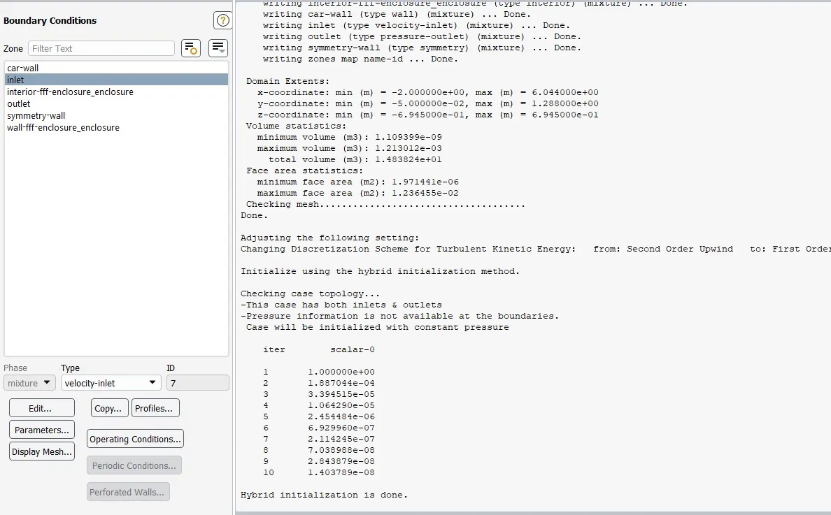
We did initialization so we got after 10 iteration the hybrid initialization is done, then the simulation run up to 2000 iteration for each and every setup.
Case-2
Results:-
Residual Plot:-
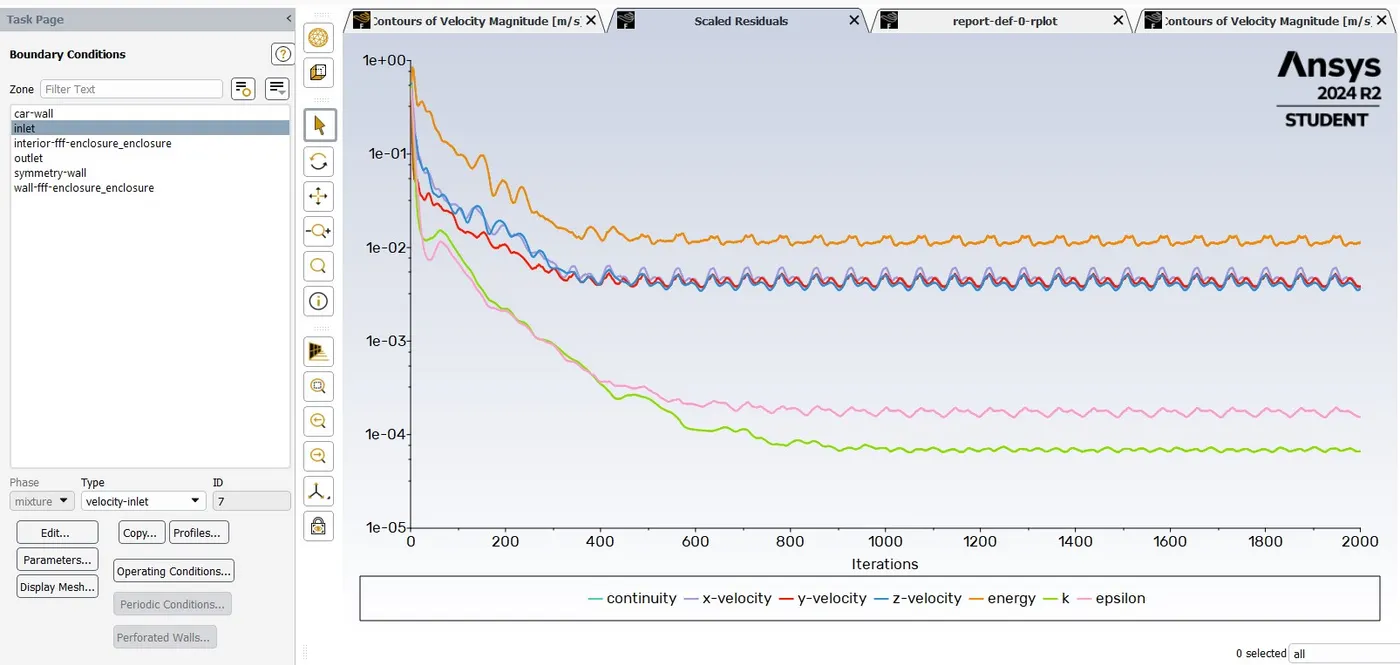
Here we can see after 1200 iteration the solution is converged.
Drag Coefficient:-
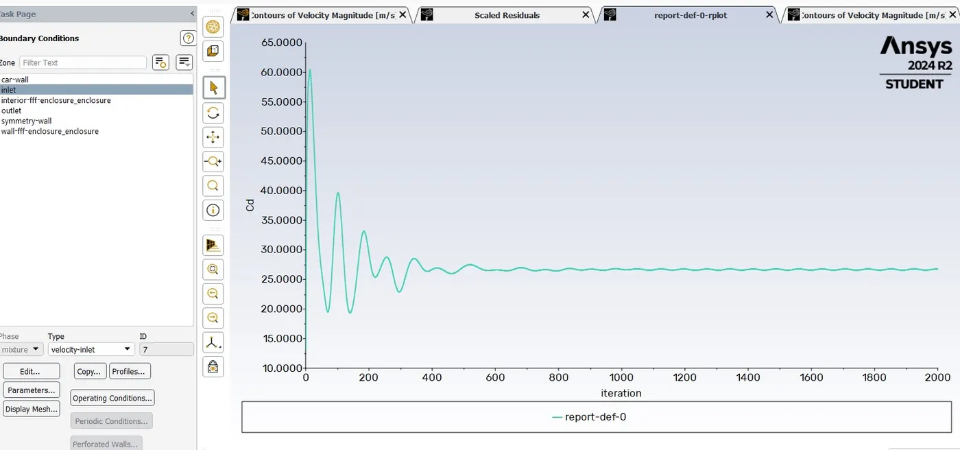
Cd=0.32579807
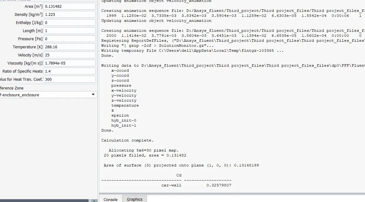
Velocity Contour plot:-
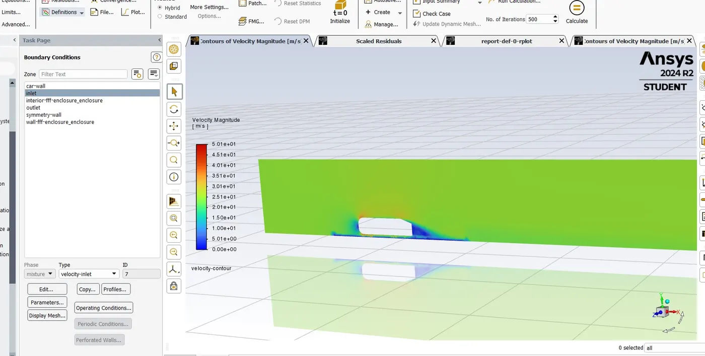
Pressure on car wall:-
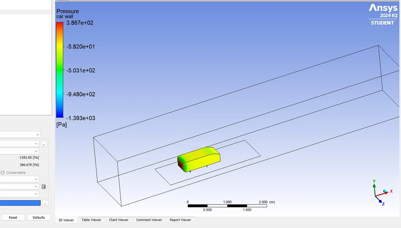
Velocity contour cut plane Z :-
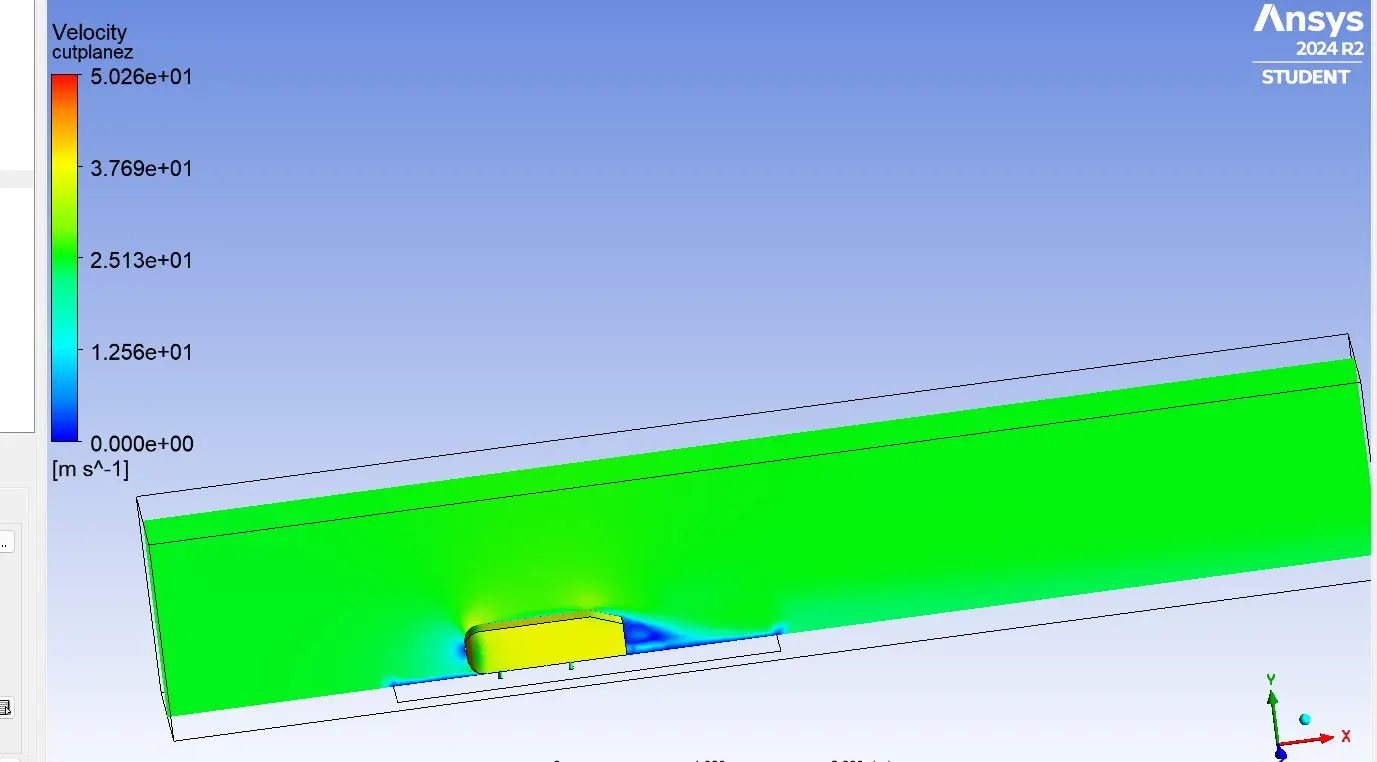
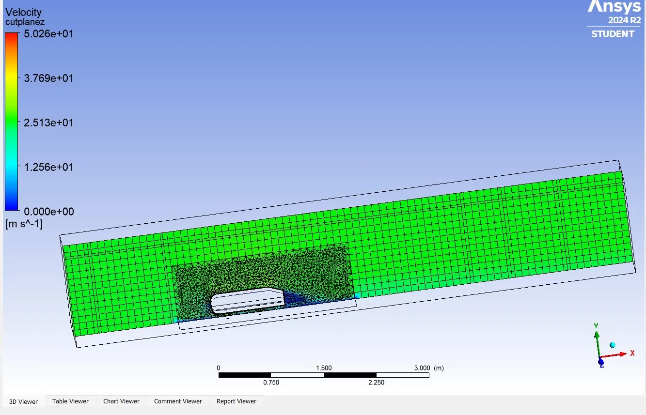
Velocity contour cut plane Z with meshing:-
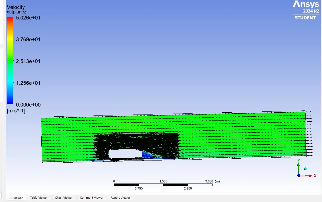
Vector plot :-
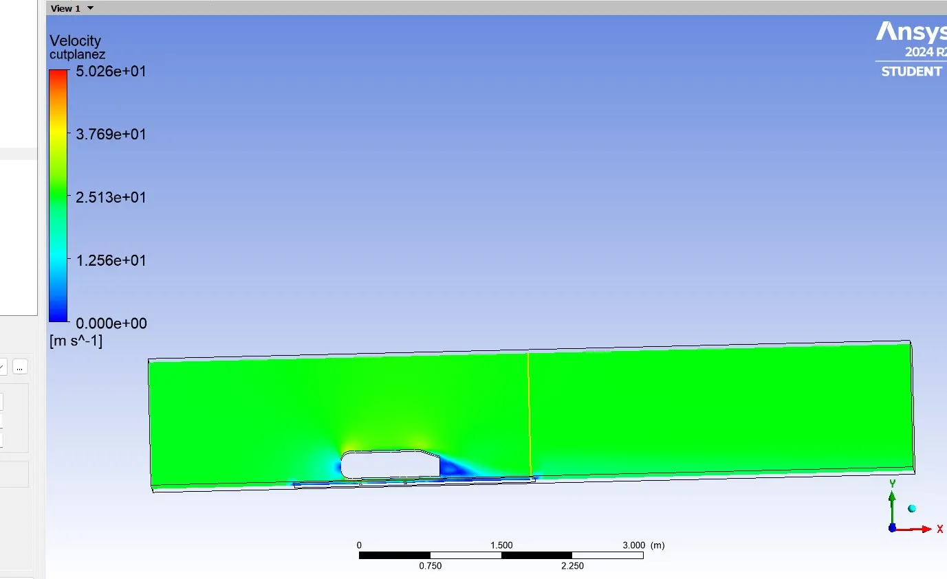
Line 1:-
Line 2:-
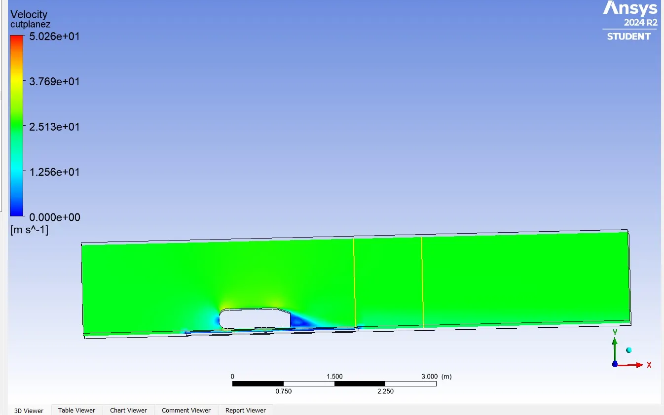
Chart line1:-
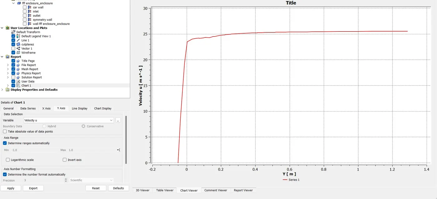
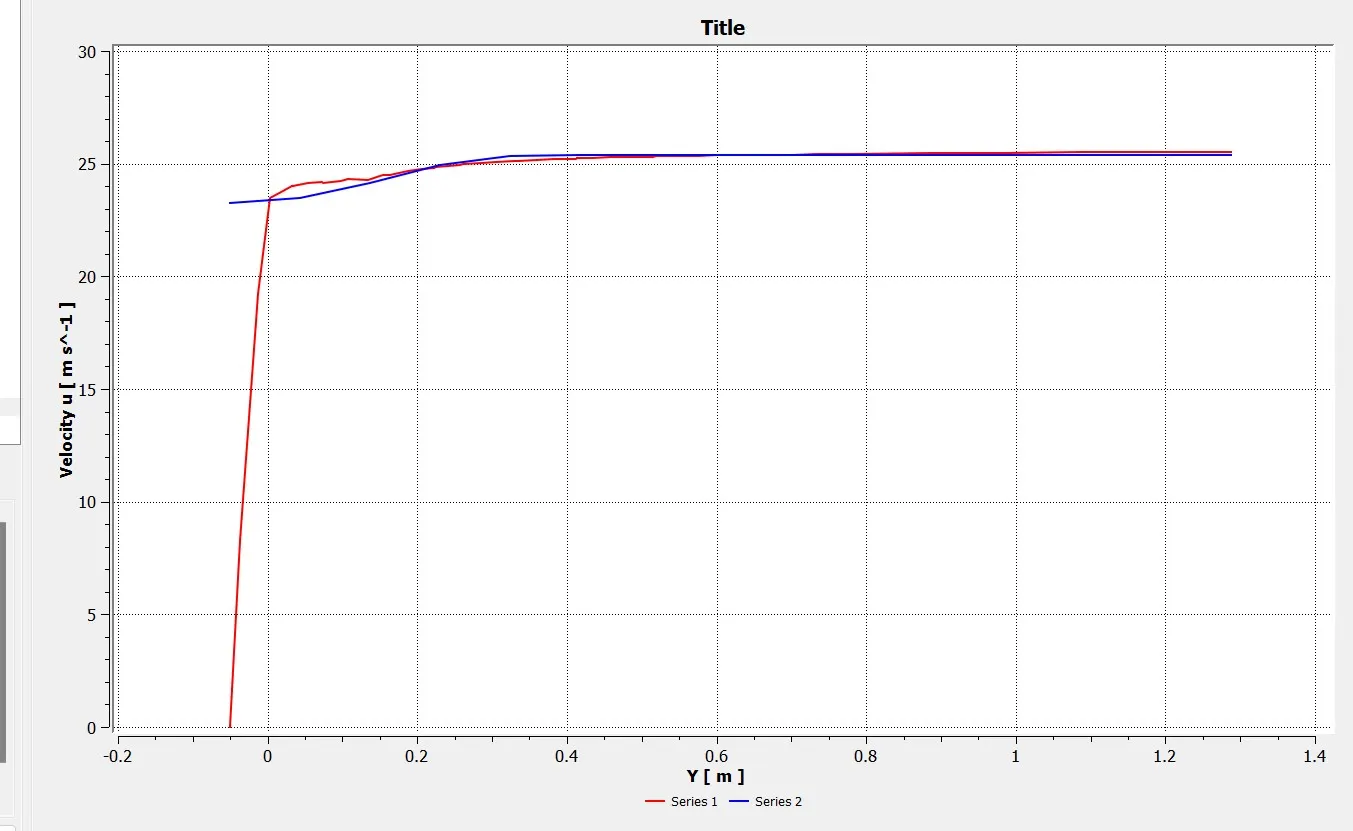
Chart line 2:-
Case 3:-
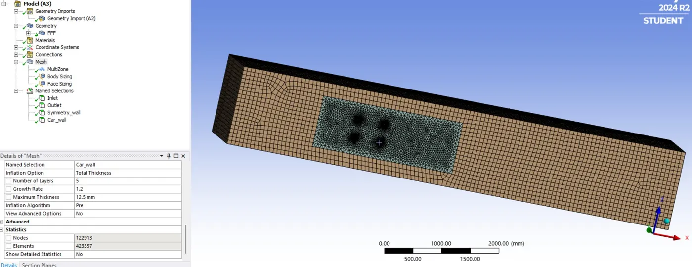
The Outer enclosure part is meshed using multizone mesh method to get accurate results based on the shape of the enclosure and its fits tetrahedral mesh and normal mesh wherever it needed in the model. The inner enclosure is meshed with default mesh.
For outer enclosure= 80 mm(multizone)
inner enclosure = 40 mm (default mesh)
No of iteration layers= 6, with first layer thickness using Y+ of 50.
After that we did section of the body, Then we started the named selection.
Inlet
Outlet
Symmetry wall
Car wall
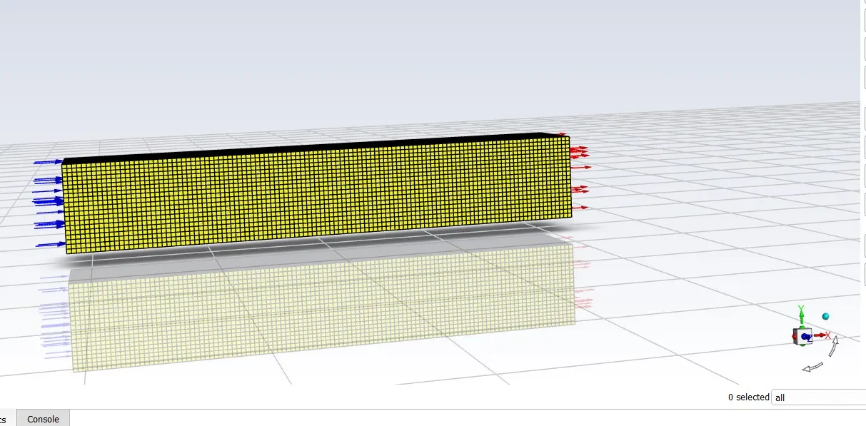
The mesh also carried by using named selection option in stead of geometry. After we started the setup then the solver is pressure based type and velocity are absolute.
Slover type Pressure based
Velocity Formulation Absolute
Time Steady state
Viscous Model K-Epsilon
Area 0.115032m^2
Length 1.044m
Density 1.225kg/m^3
Dynamic viscosity 1.7894e-05kg/ms
Pressure 0pascal
Method Hybrid Simulation
Inlet Velocity 25m/s
Material Fluid-air
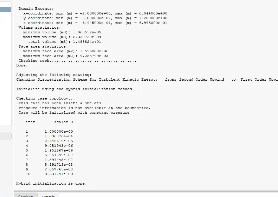
We did initialization so we got after 10 iteration the hybrid initialization is done, then the simulation run up to 2000 iteration for each and every setup.
Case-3
Results:-
Residual Plot:-
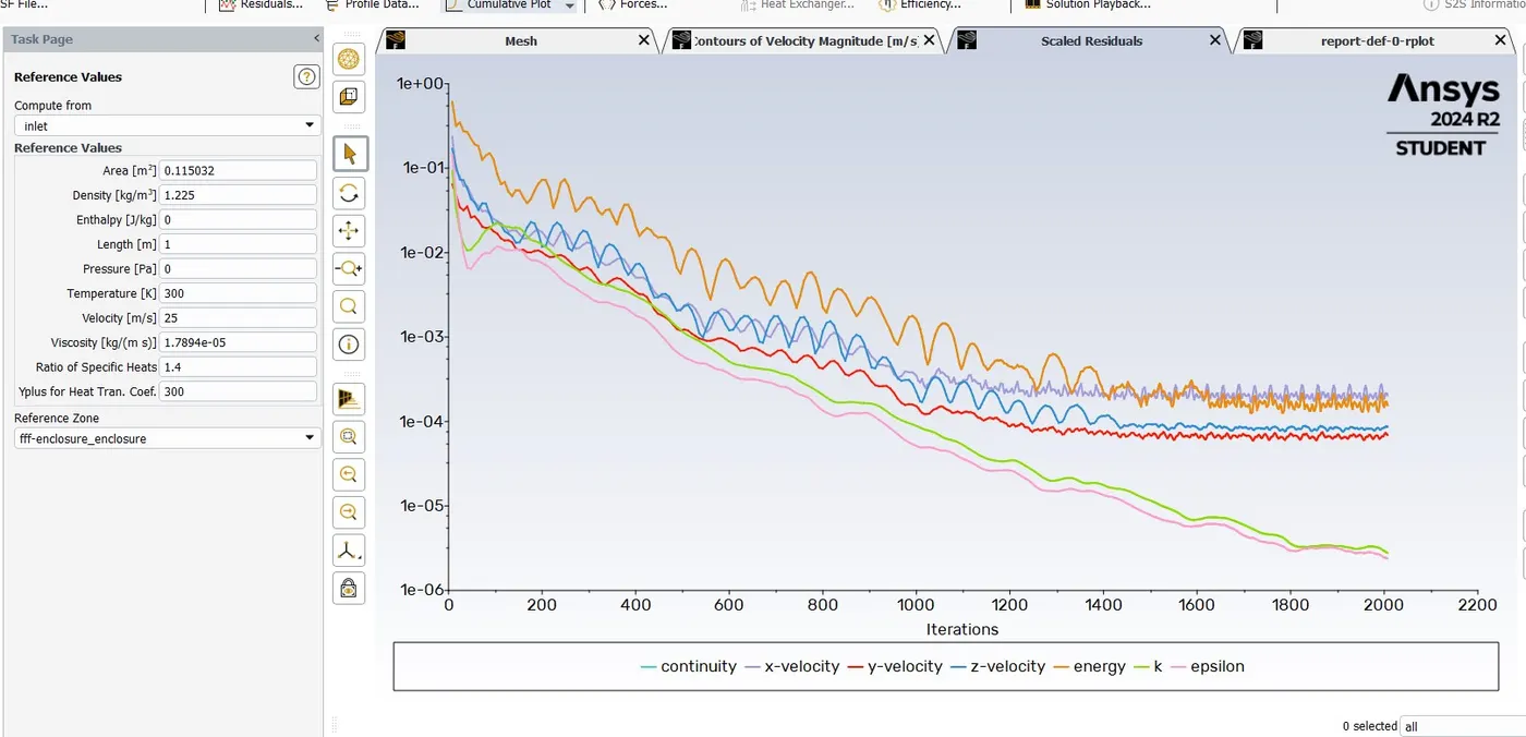
Here we can see after 1800 iteration the solution is converged.
Drag Coefficient:-
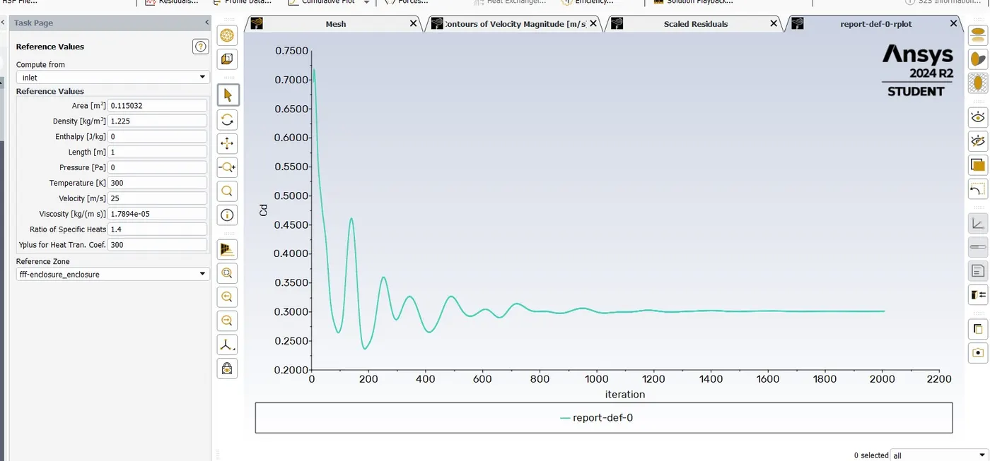
Cd=0.34441015
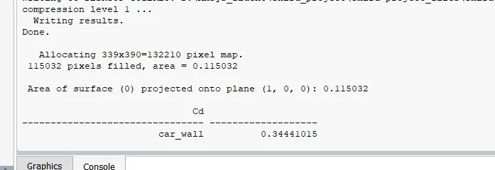
Lift Coefficient:-
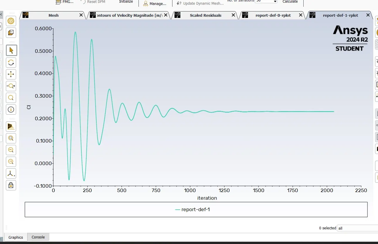
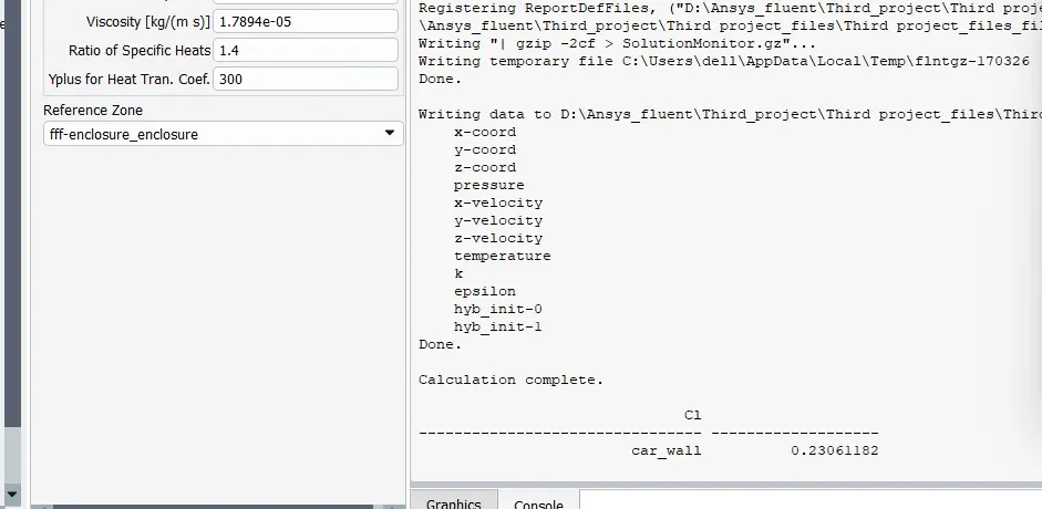
CI=0.23061182
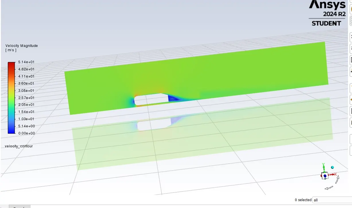
Velocity Contour plot:-
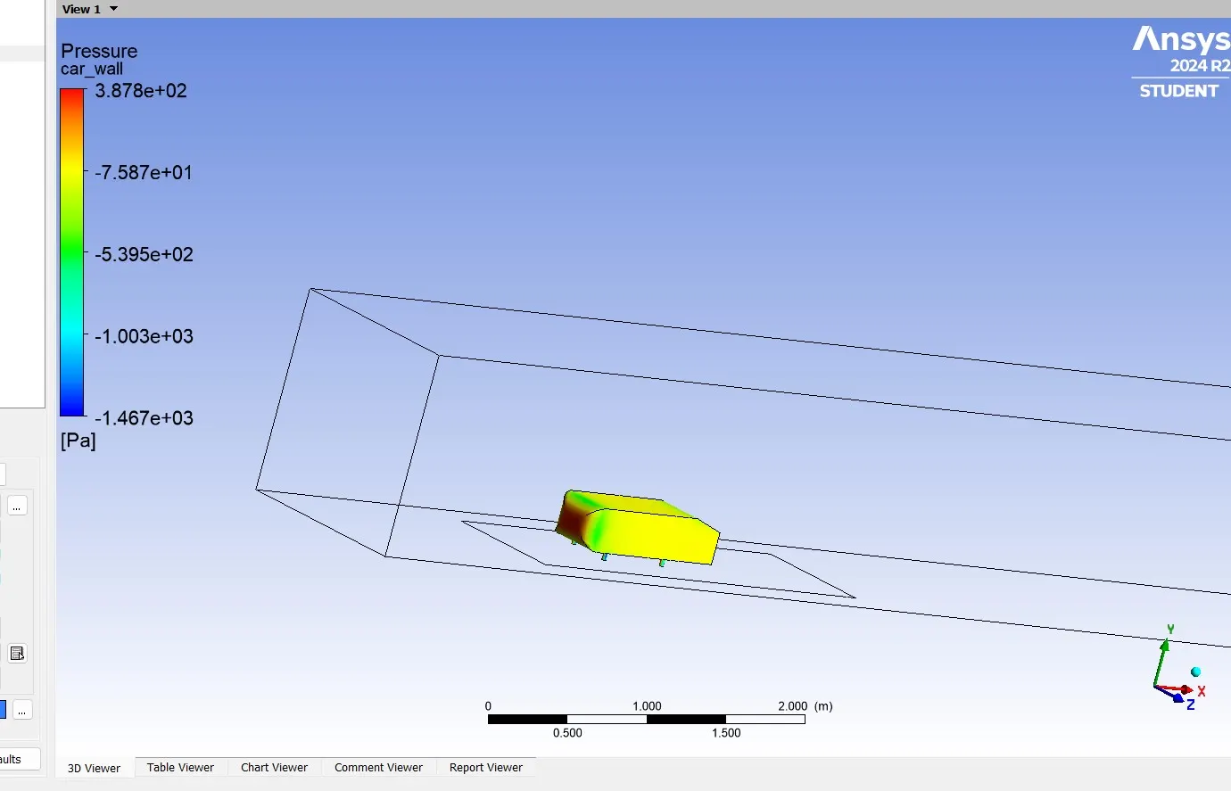
Pressure on car wall:-
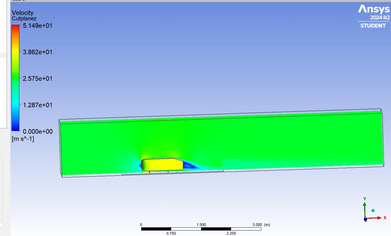
Velocity Contour cut plane Z:-
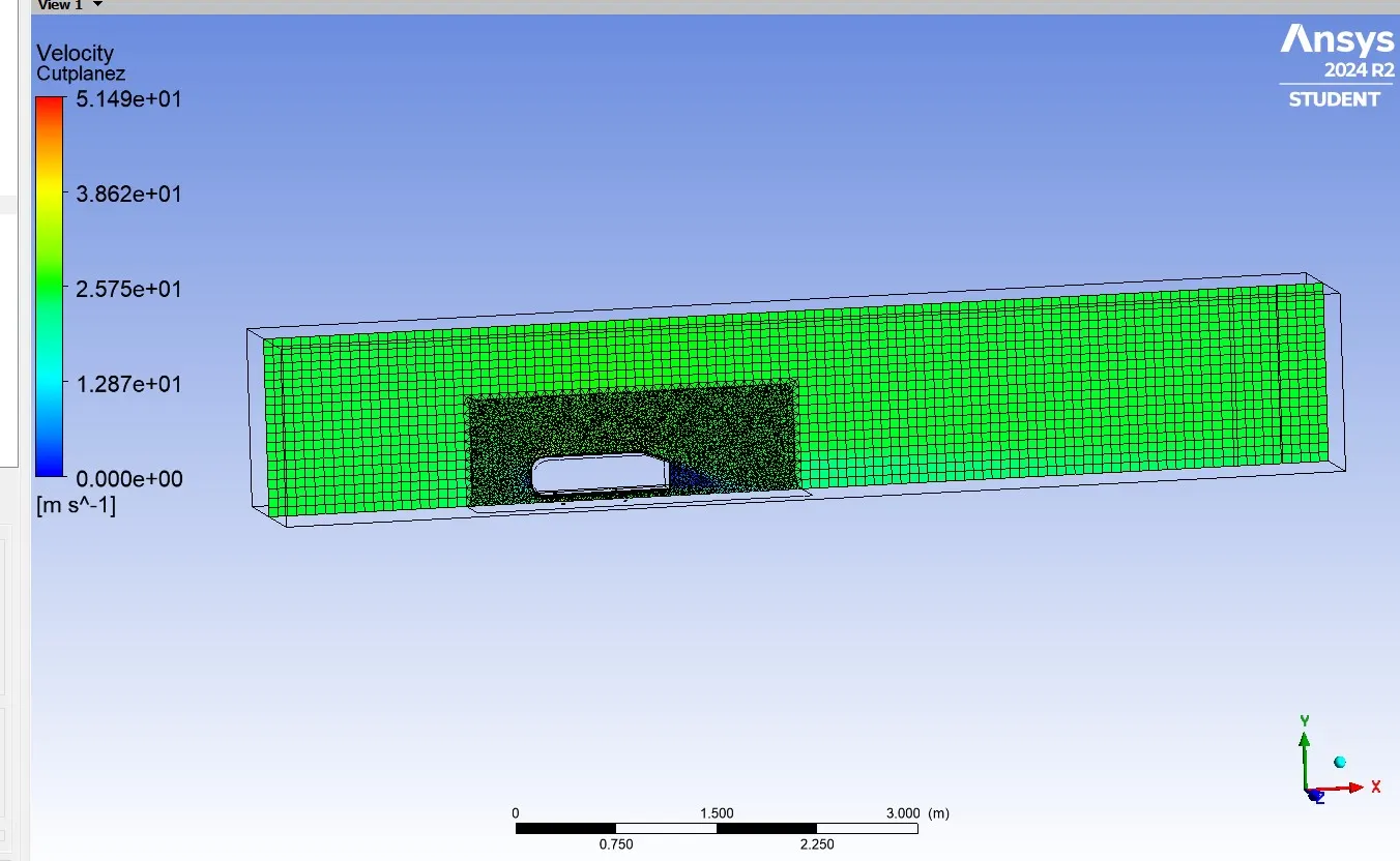
Velocity Contour cut plane Z with meshing:-
Vector plot:-

Chart line 1:-
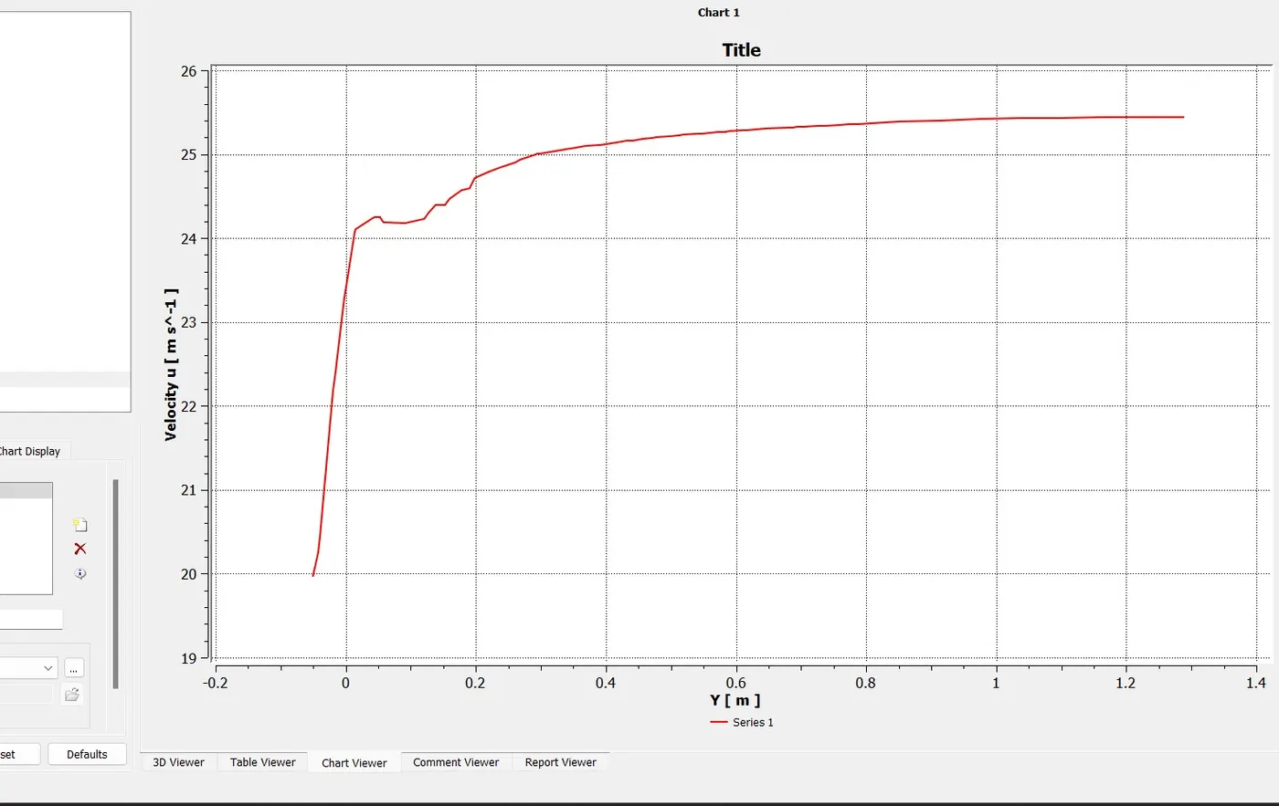
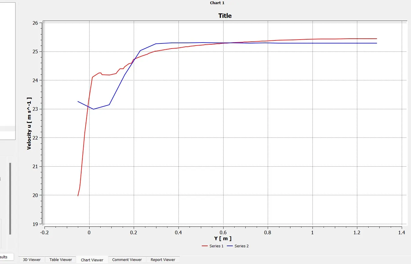
Chart line 2:-
Hence the smaller the element size the mesh will be more refined and drag value will be near to the accurate value, possibilities of error will be less. As we discussed above, the flow detached from the Ahmed body produces vortices and creates negative pressure in the wake region, that place point is the separation of the flow.