Week 3 - External flow simulation over an Ahmed body.
Ahmed body:-
The Ahmed body is like a basic toy car model used to test computer programs that simulate how air flows around cars. Because it's simple and there's a lot of information about it, scientists and engineers use it to make sure these computer programs are working correctly. This helps them understand how real cars interact with the air and make better designs.
Negative pressure regions and separation point:-
Negative pressure regions and separation points are areas where the pressure of air around an object drops below the surrounding atmospheric pressure. In simple terms, they're spots where the air "sucks in" rather than pushes out. Separation points occur when the air flow around an object detaches from its surface, creating pockets of low pressure. These phenomena are crucial in understanding how air flows around objects like cars and airplanes, as they affect things like lift and drag.
EXAMPLE:-
Let's think about a paper airplane. When you throw it, air rushes over its wings. But if you crumple the back edge of the wings, the air might not flow smoothly anymore. Instead, it might break away from the wings, creating low-pressure pockets. These pockets pull the plane backward or make it drop faster. That's what we mean by separation points and negative pressure regions—they're where the air doesn't stick to the surface anymore, causing tricky effects like drag or loss of lift.
Procedure/steps to solve:-
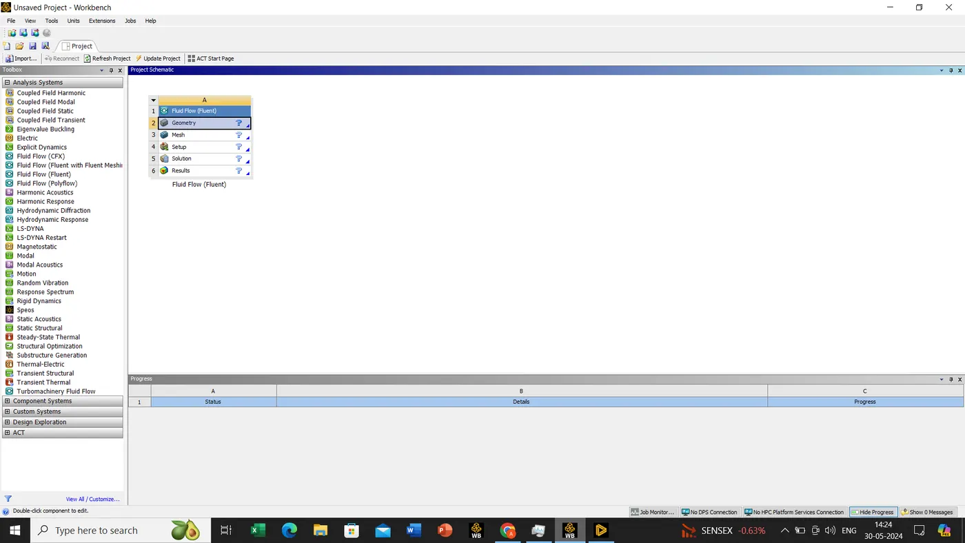
First we will open our workbench and later we will drag & drop fluid flow fluent, double click on geometry to open a new workspace. once the ansys discovery/spaceclaim is opened we will drag and drop our model for work.
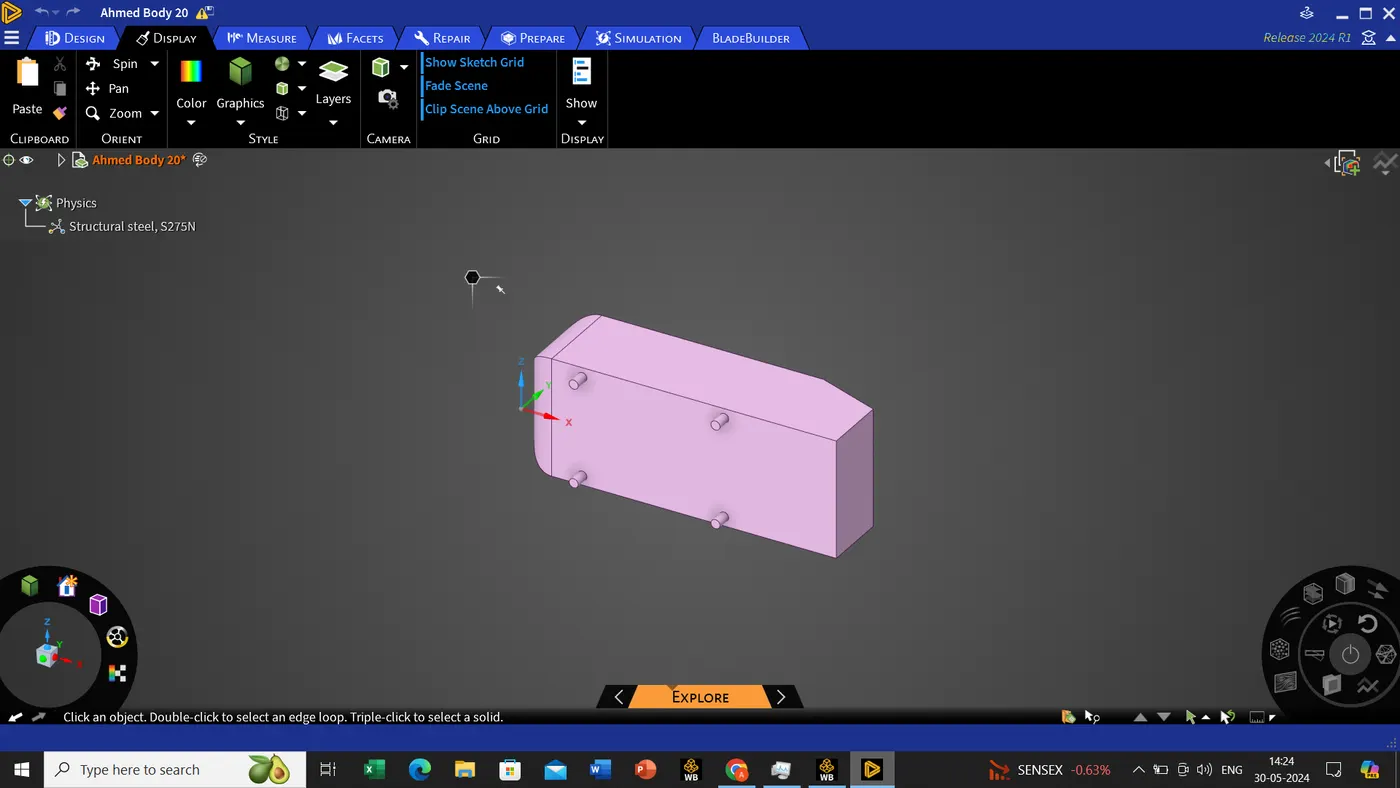
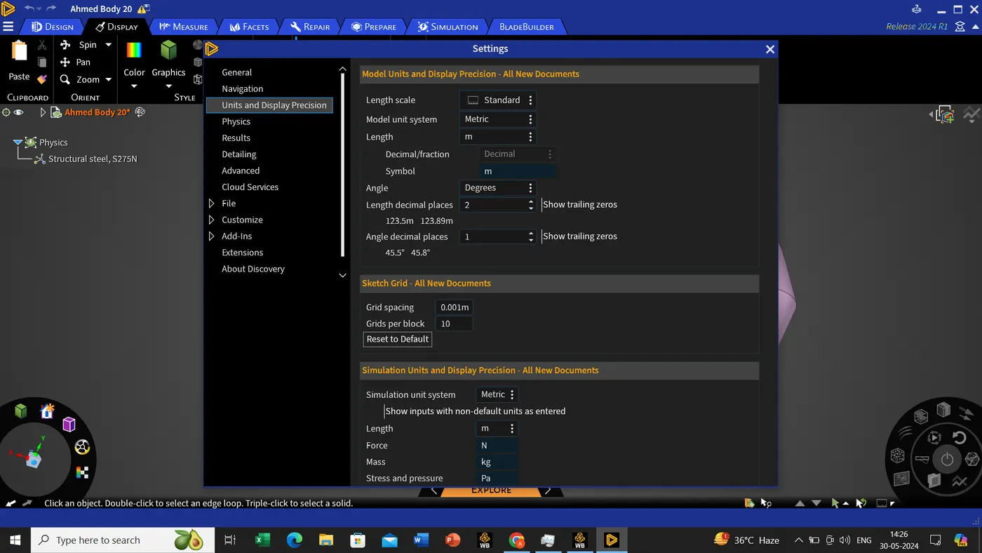
The unit shall be in meter for this model for my convenient.
file->settings->units and display precision.
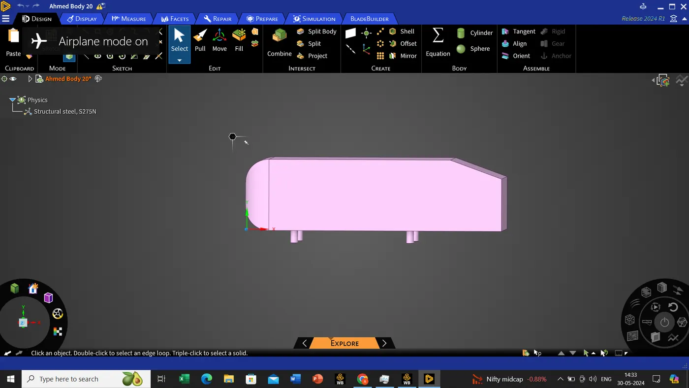
We don't need to mesh inside the ahmed body, so for this we should be creating a wall , since its prevent the meshing
we shall be using the enclosure tool which is present in prepare ribbon->enclosure->click on the body->the dimensions will appear, since we will untick the symmetric dimensions so that we select the dimensions as per our convenient->we can see the green color tick, to create the enclosure.
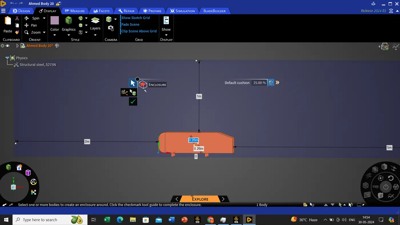
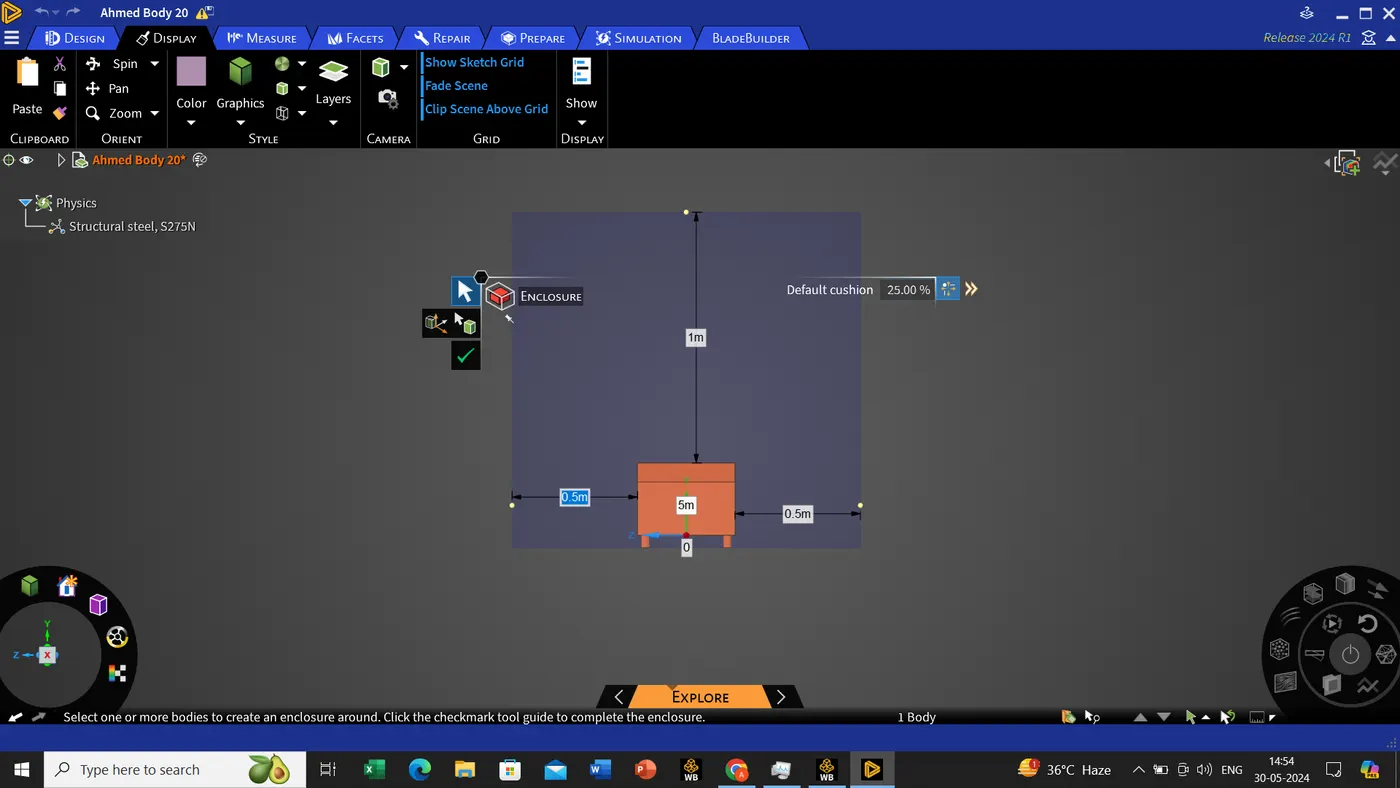
we have to create the 3 plane along the x ,y and z axis.
design tool->select the plane-> Click on the origin of the axis, the plane result is shown below.
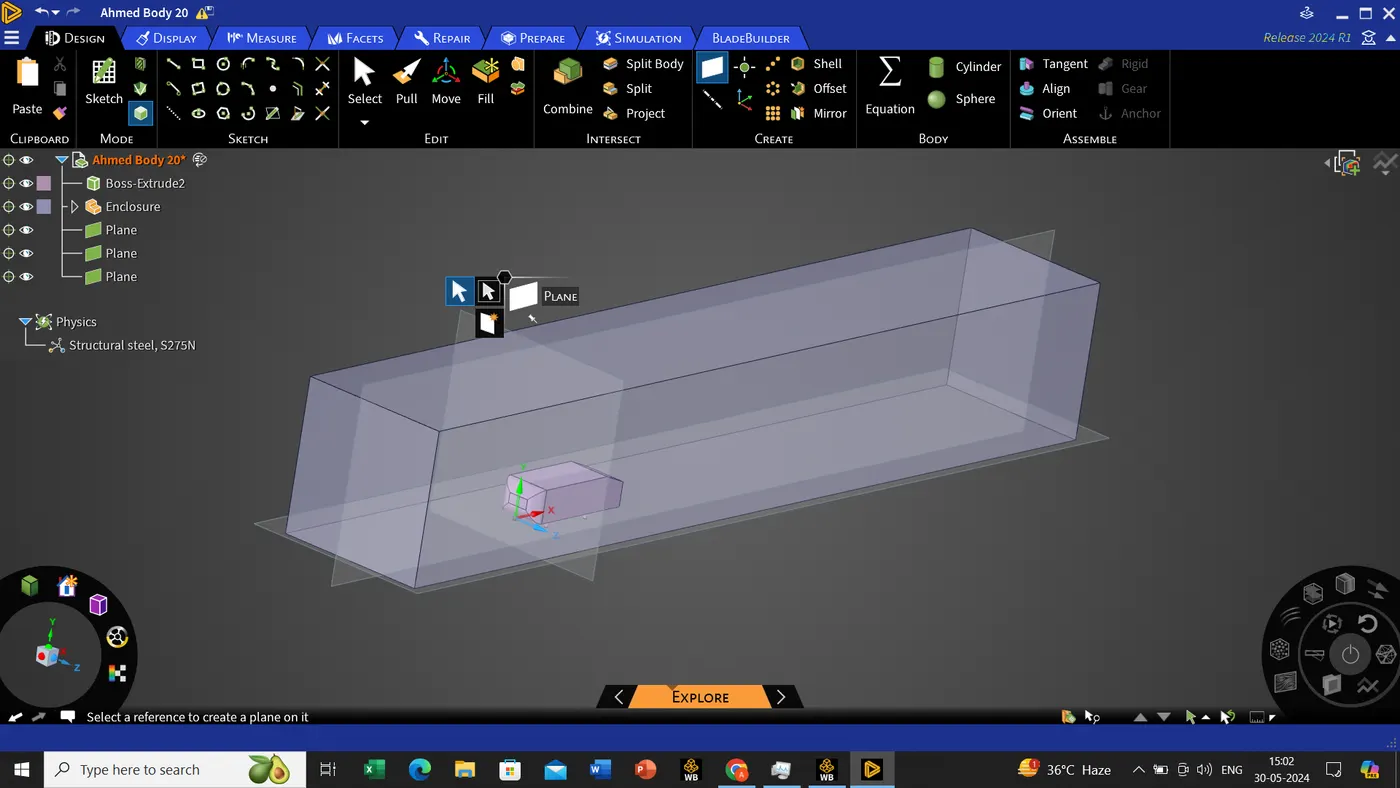
once its done we will cutting the plan with the help of enable 3d sketch which is present in the design tool itself.
design tool->select the plane, which has to be cut->select the 3D sketch and click on the plane, the result is shown below.
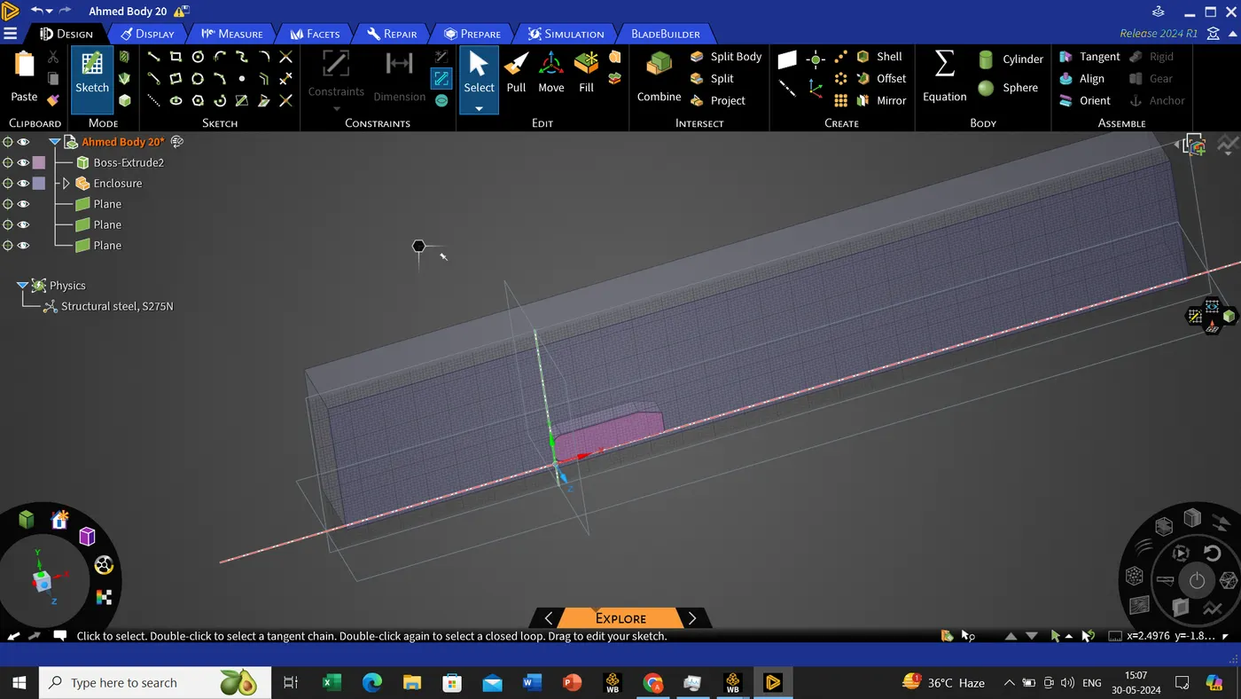
Since we have to create a new enclosure with a new dimensions as shown below,
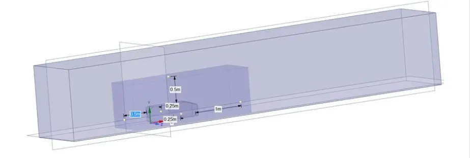
Prepare->Interference->click on the new enclosure->click on the green tick, so that it can apply.
The reason using the interference to get the symmetrical hatching.
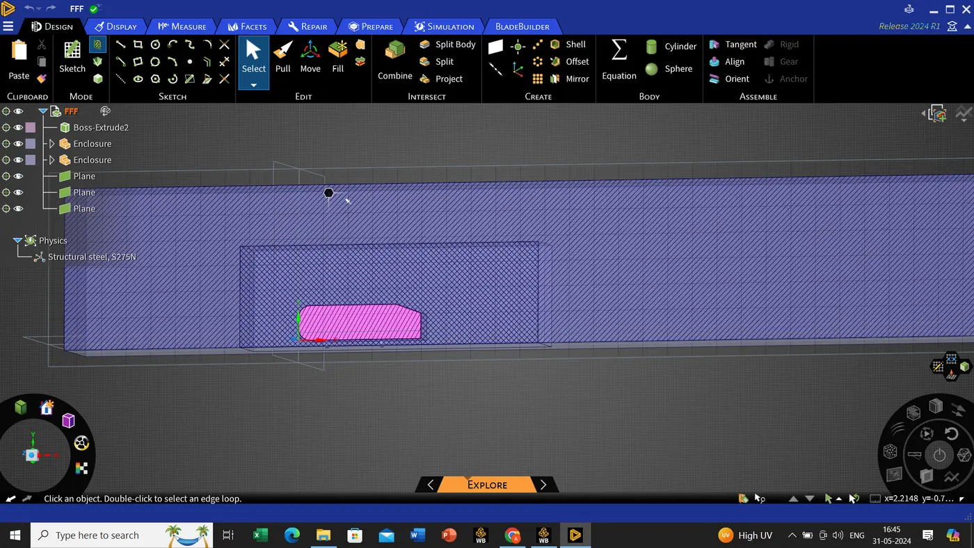
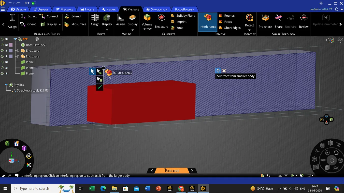

Once we are done with this we double click the main file (for this FFF*)in this we will select the share topology then it is finally ready for meshing.
Once we have done this we will be closing the geometry and opening the meshing tab.
Using the section plane,
Home->section plane, cut from the center so that we can view the car body also.
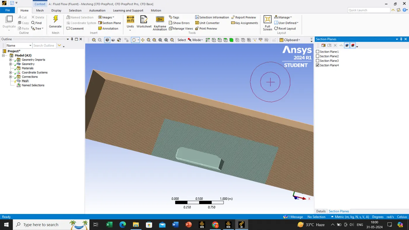
before assigning the new mesh element size we should directly generate the mesh, for better understanding.
generated mesh by ->mesh->right click->clear generated data->regain generate the mesh.
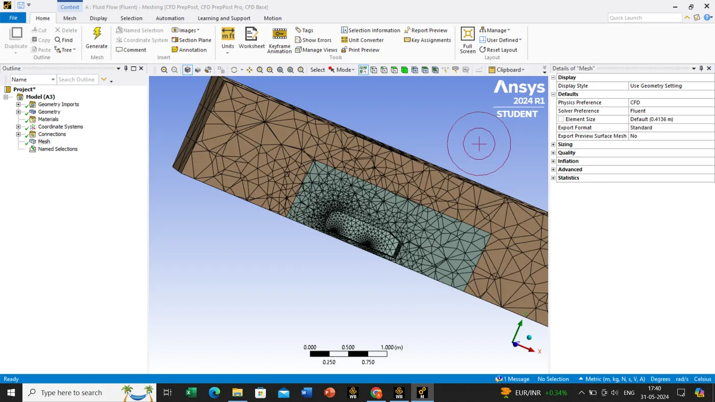
As we can see the mesh is improper so we will be regenerating the mesh by following steps.
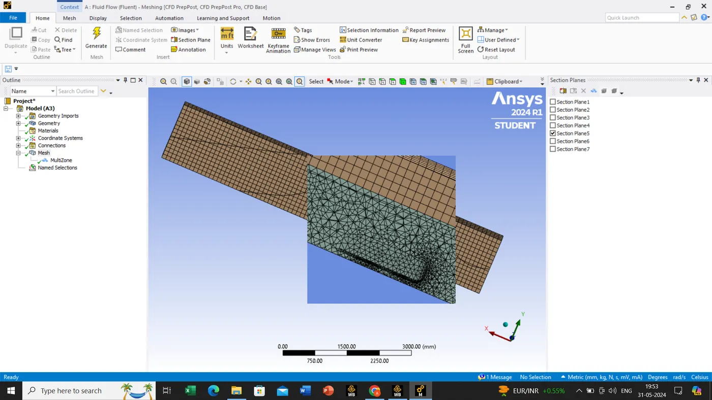
Mesh for outer enclosure->Insert->Method->select the body phase and apply the geometry->definition->method=multizone->In main mesh-> defaults=element size(100mm)->sizing=max size(100mm)
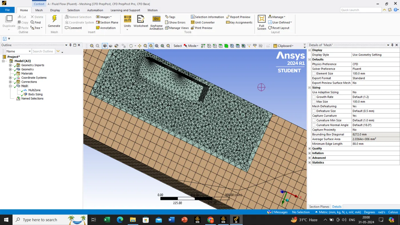
mesh for inner enclosure->insert->sizing->select the geometry and apply->input the element size =50mm->generate the mesh
now we will be assigning the walls.
face tool->select the face->click N or else click the right mouse button to the see the options in that we can see create the name selection.
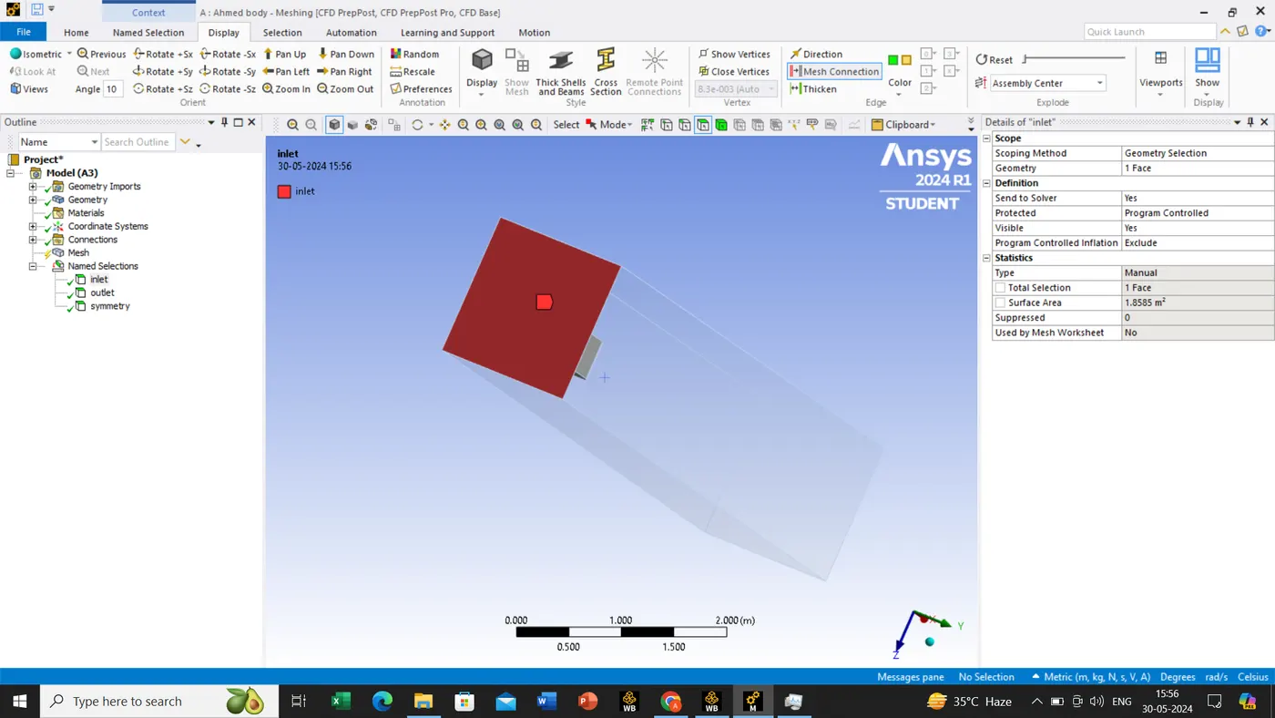
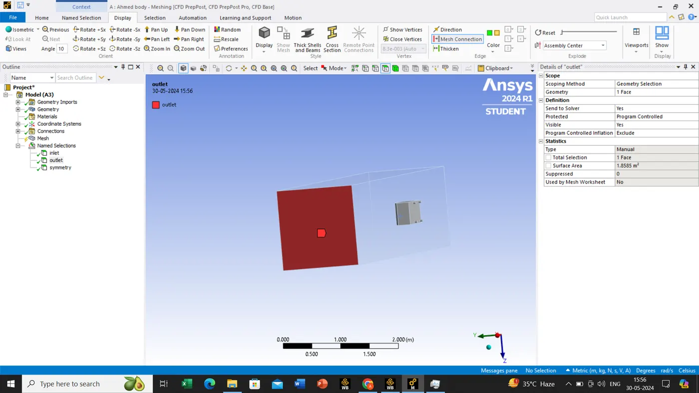
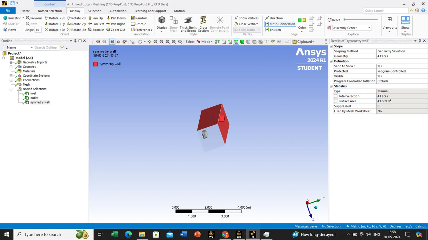
before selecting the car wall we should use the button F8 to hide the plane->select the box->select the car->enter the N button and assign the name.
now we are moving to the setup tab by closing the meshing tab.
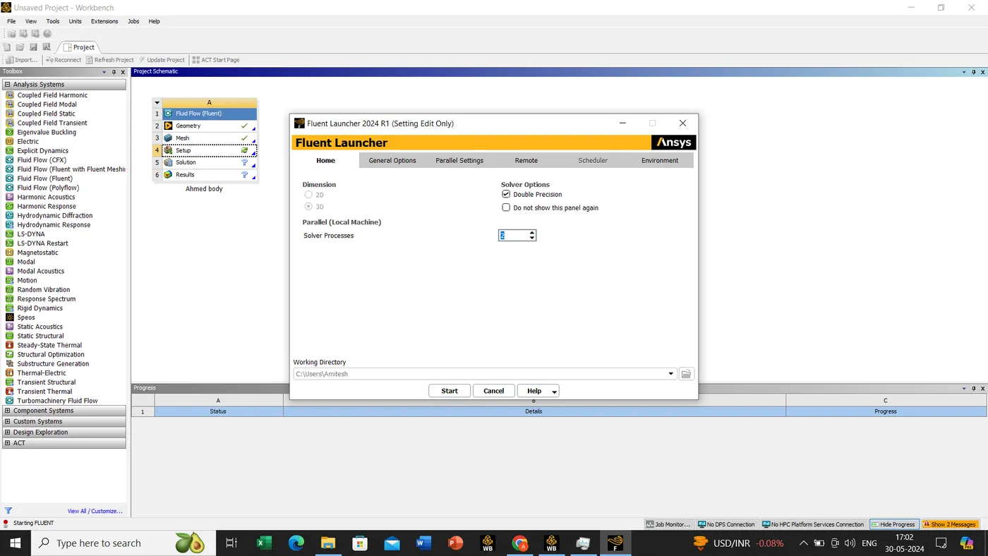
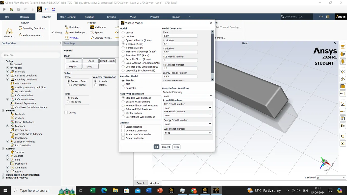
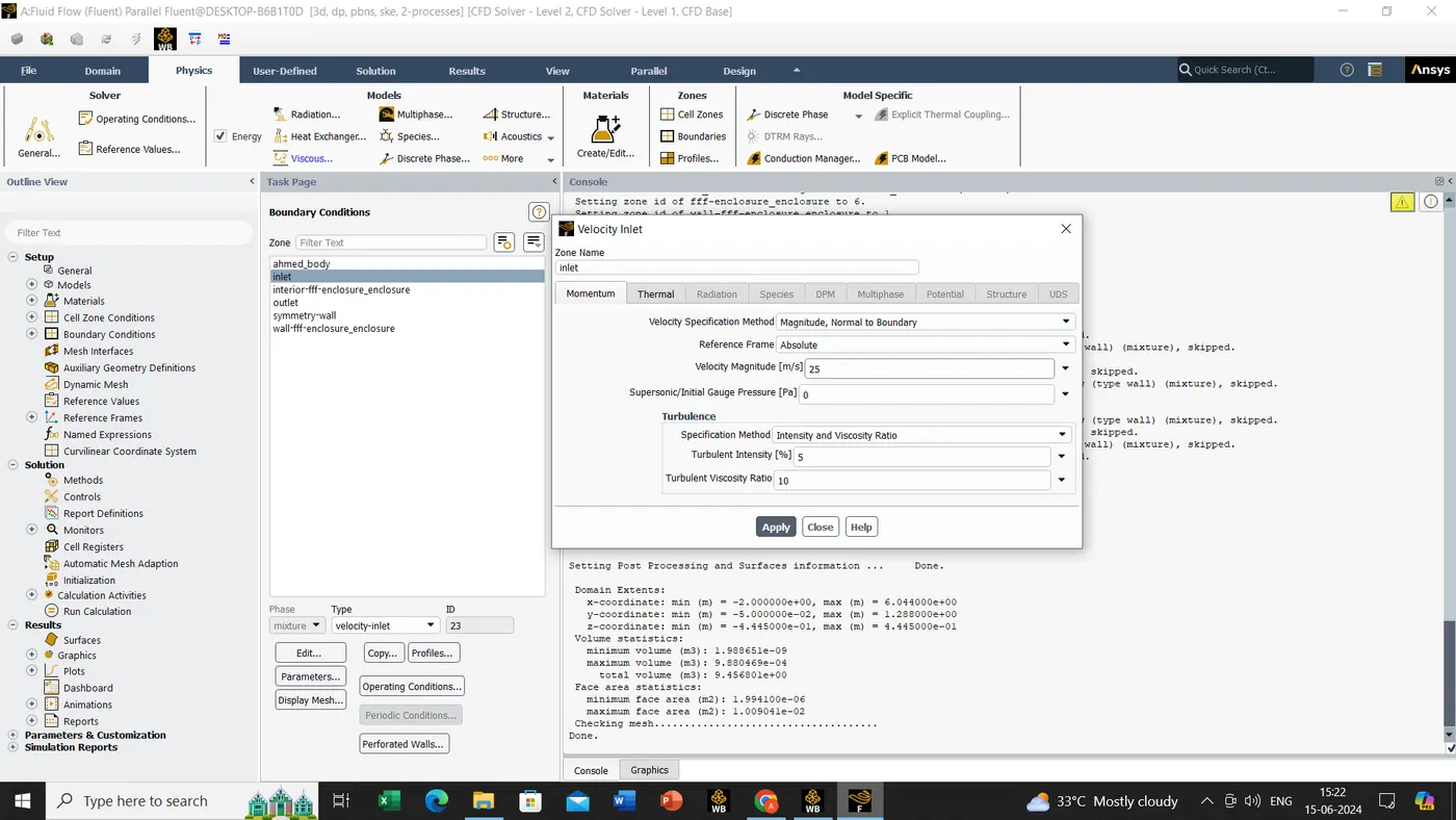
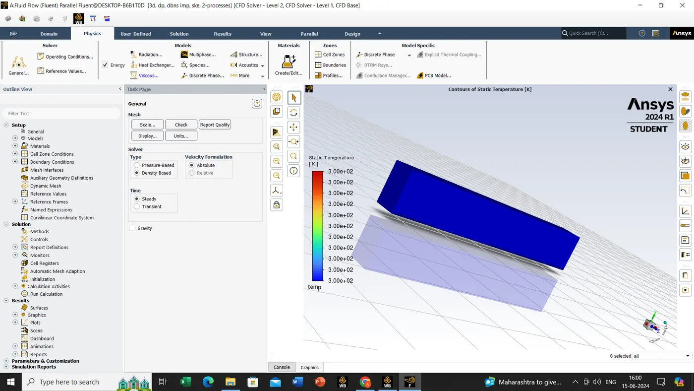
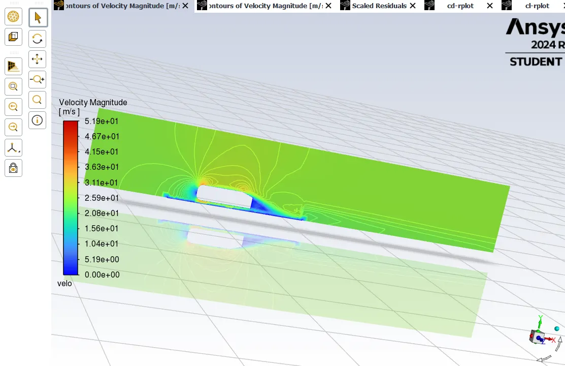
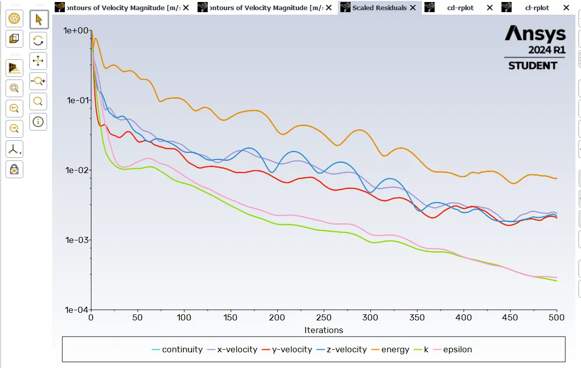
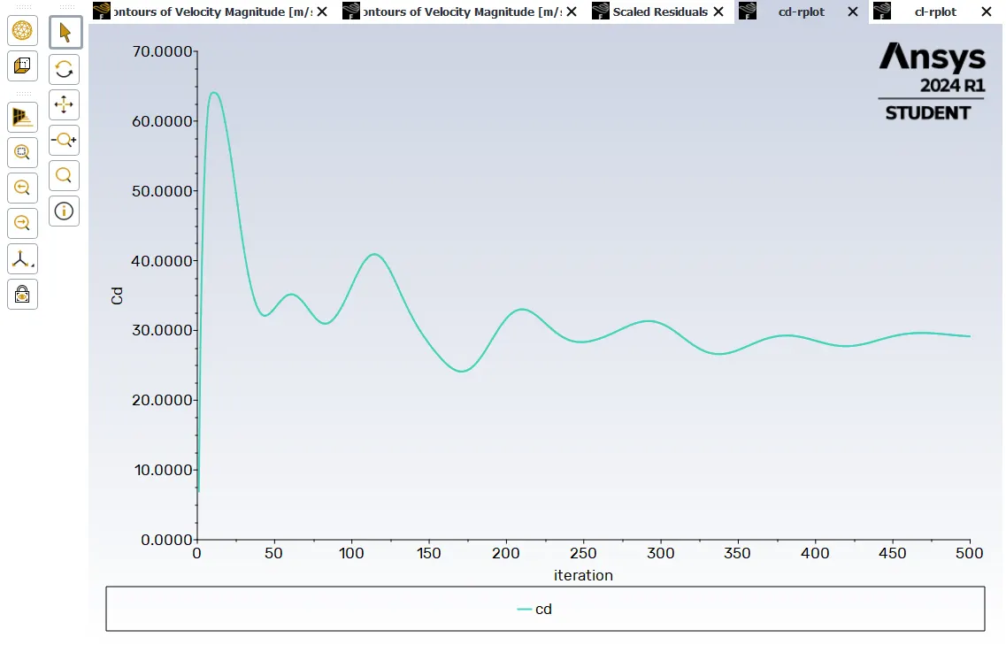
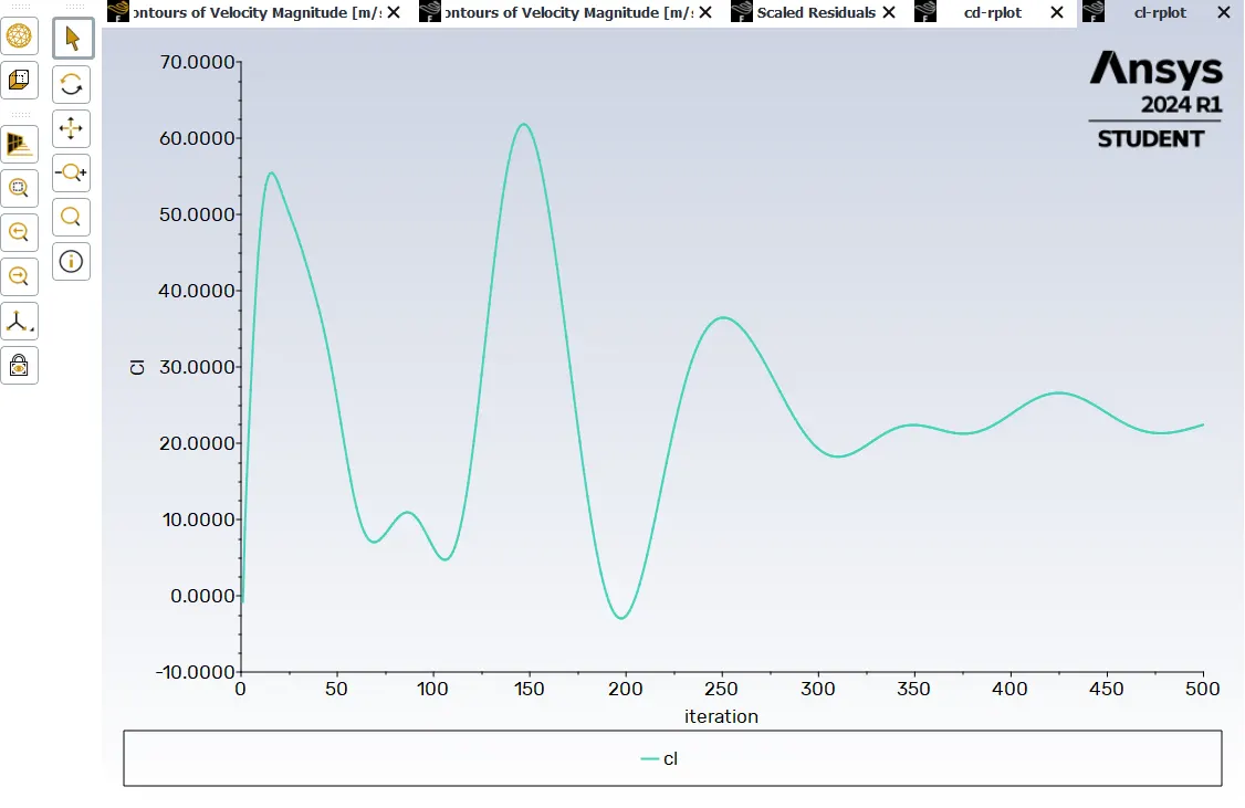
now we are moving to the Result tab by closing the ANSYS fluent tab.
we will select only ahmed body and double click on it and select the variable in that go for the pressure and hit the button apply.
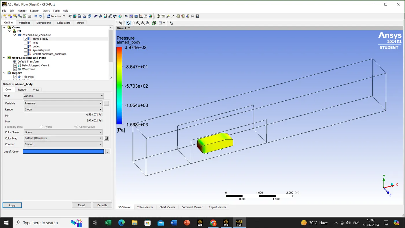
we will be creating the plane.
insert->location->plane->assign the plane name as a cut plane.
Geometry->The plane shall be on XY plane and later apply it.
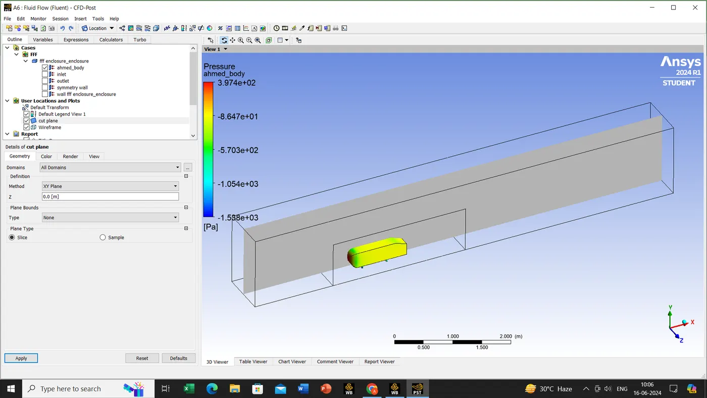
color->select the variable->select the velocity->apply it.
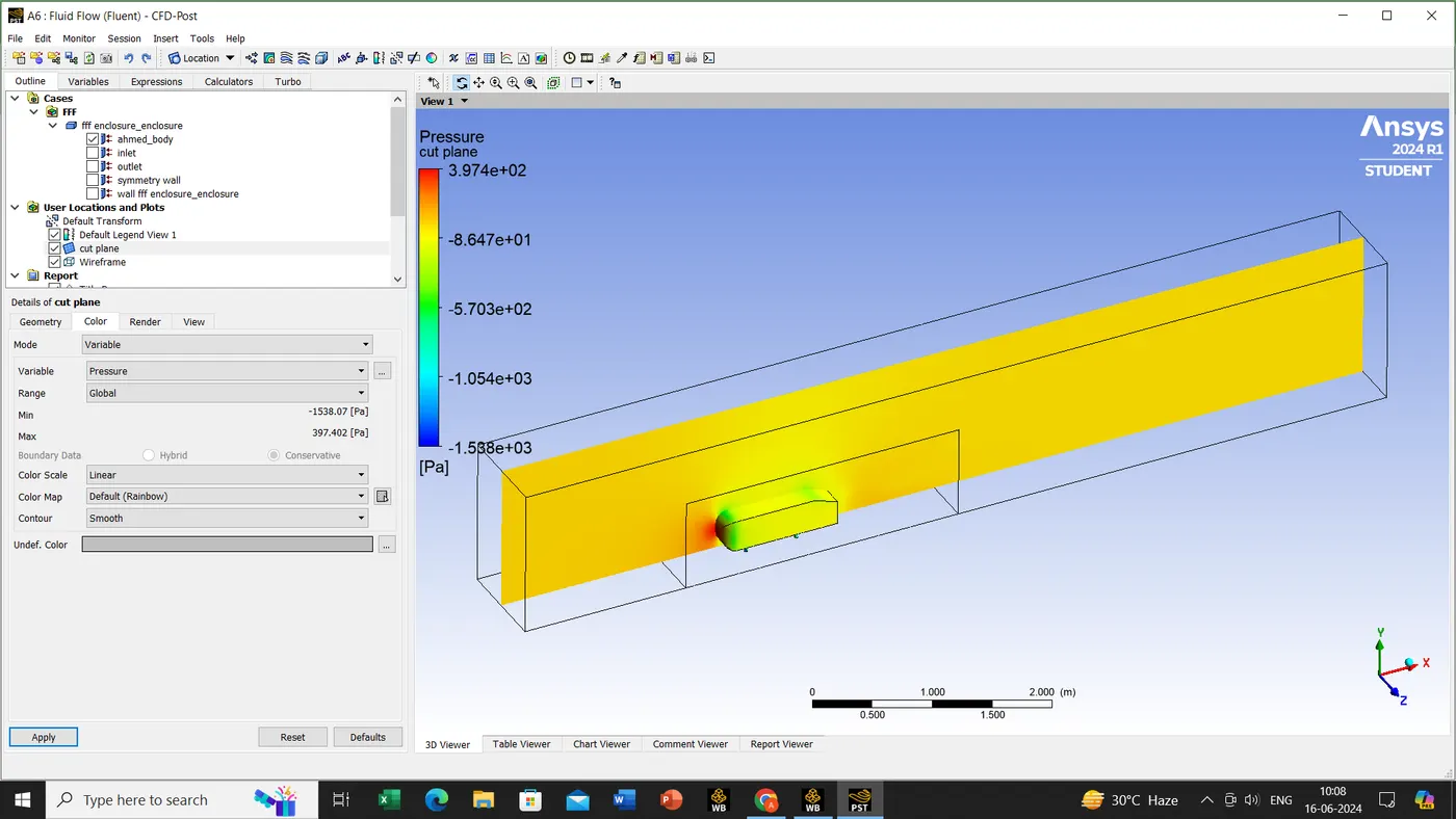
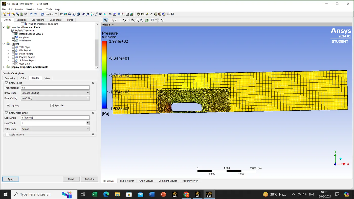
Now untick the ahmed body->render->active the mesh line.
click on the vector which is present in the toolbar.
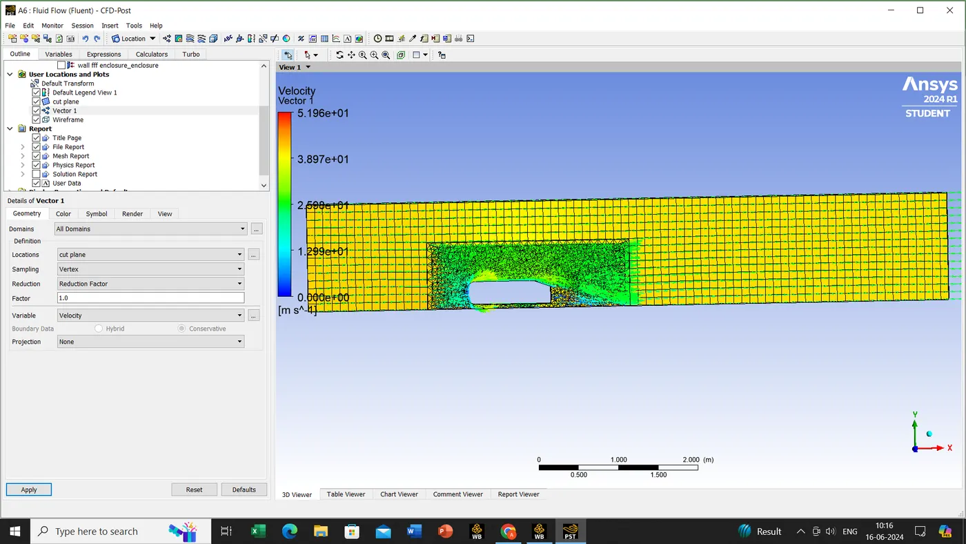
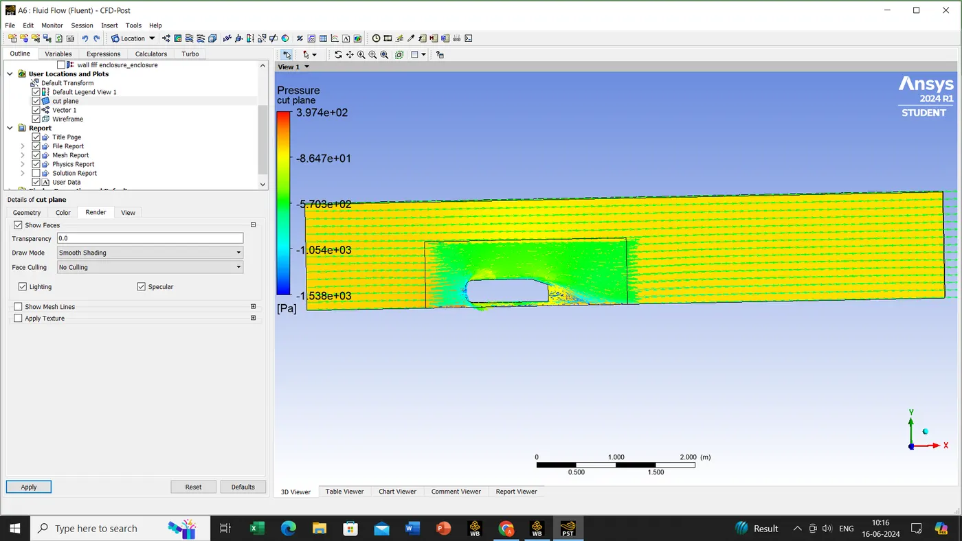
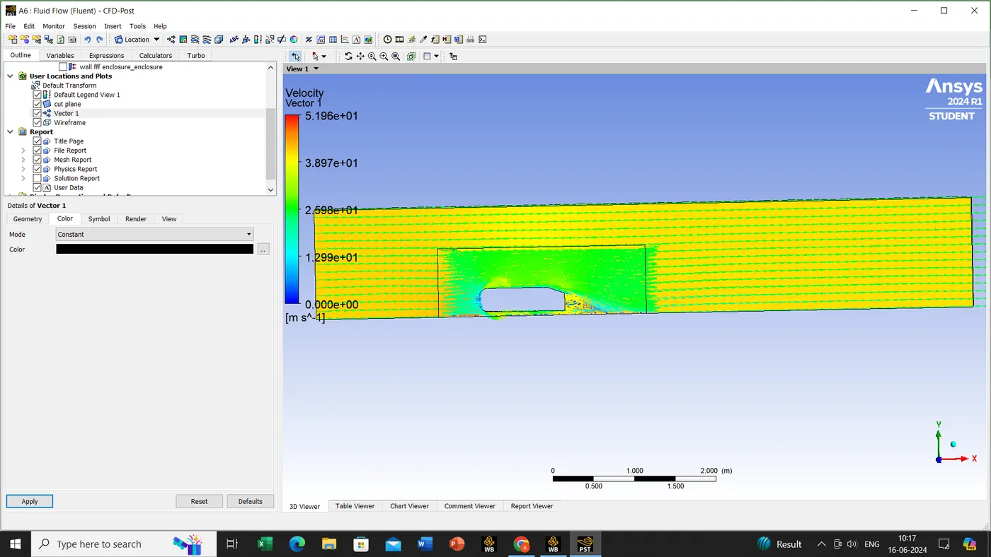
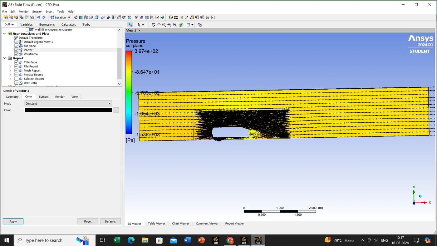
now untick the vector1 and create a line
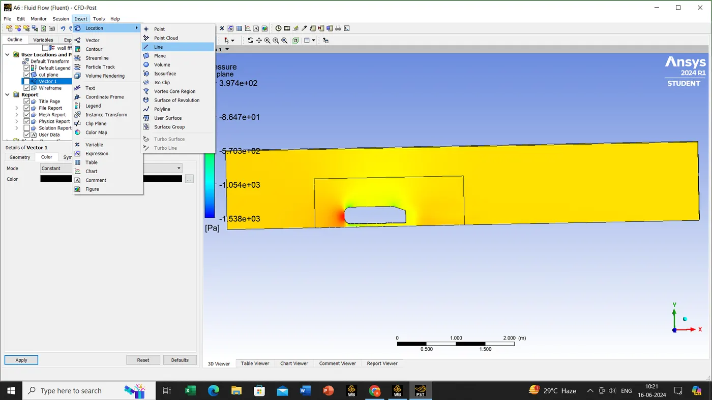
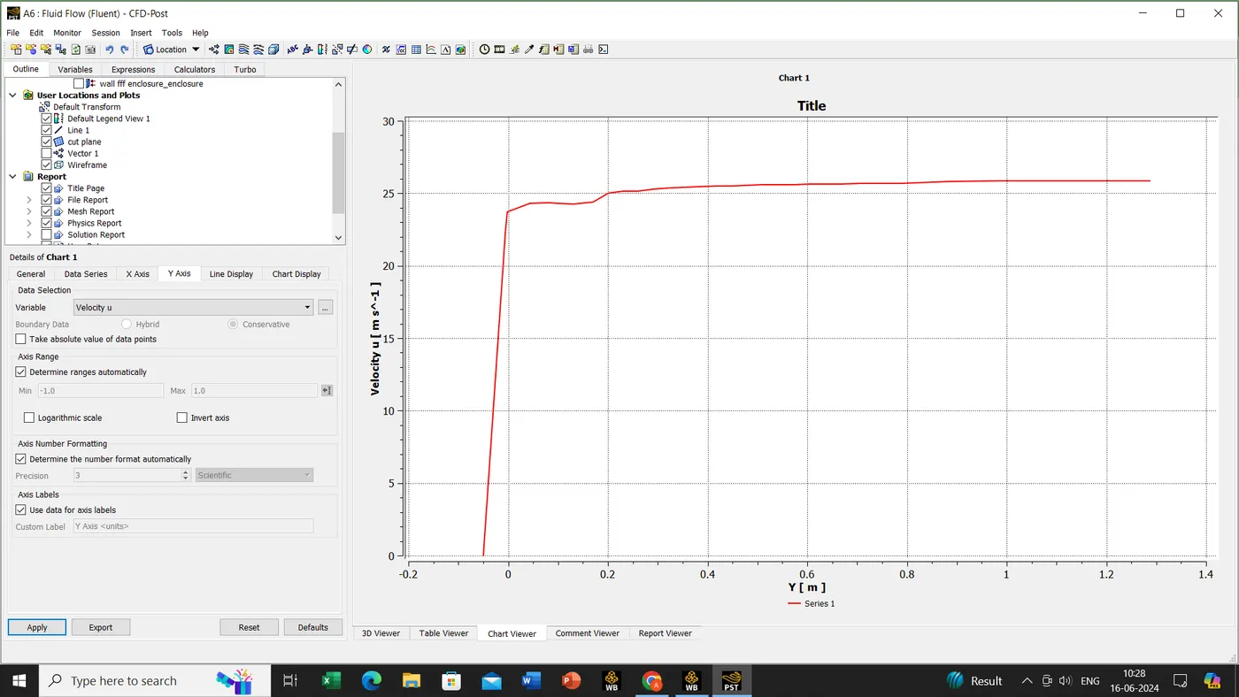
insert->chart create.
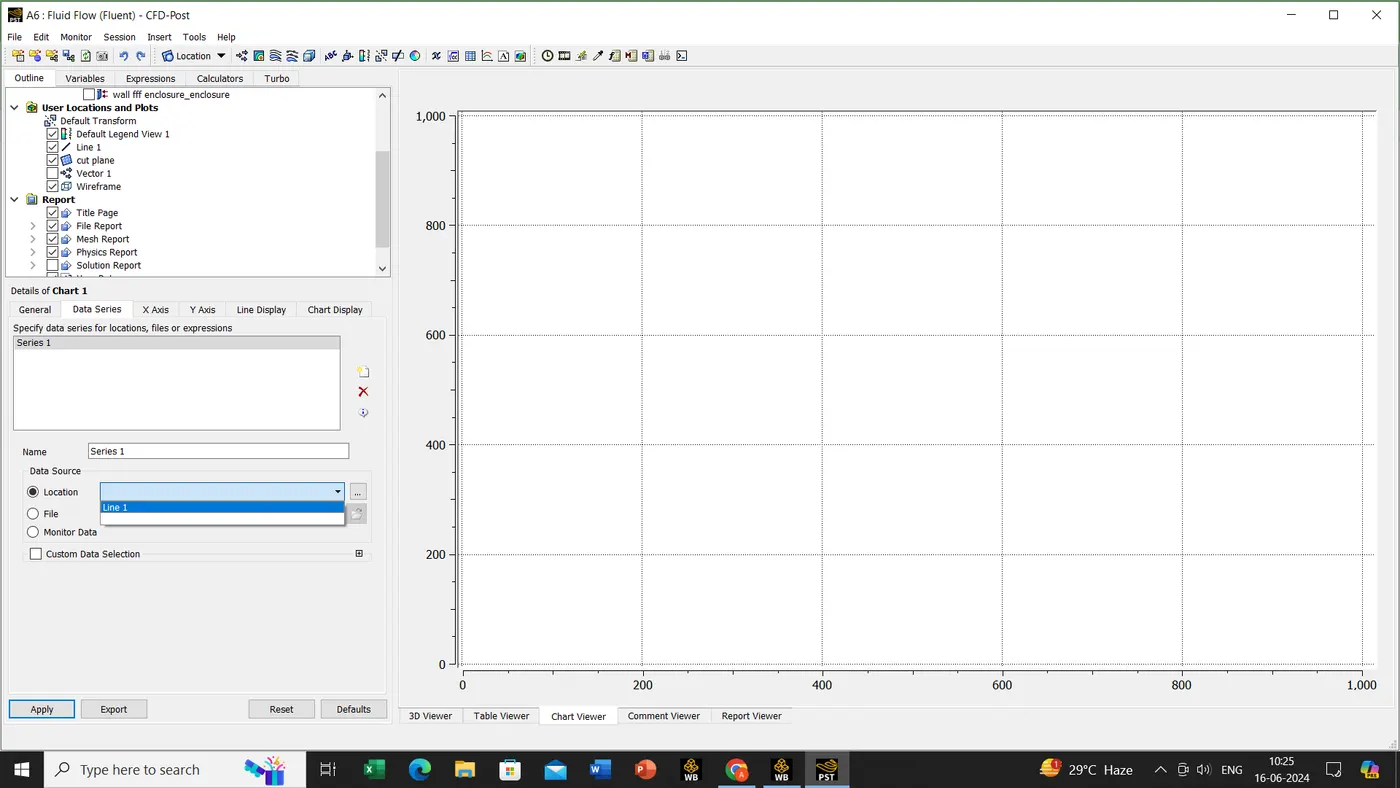
data series->line 1
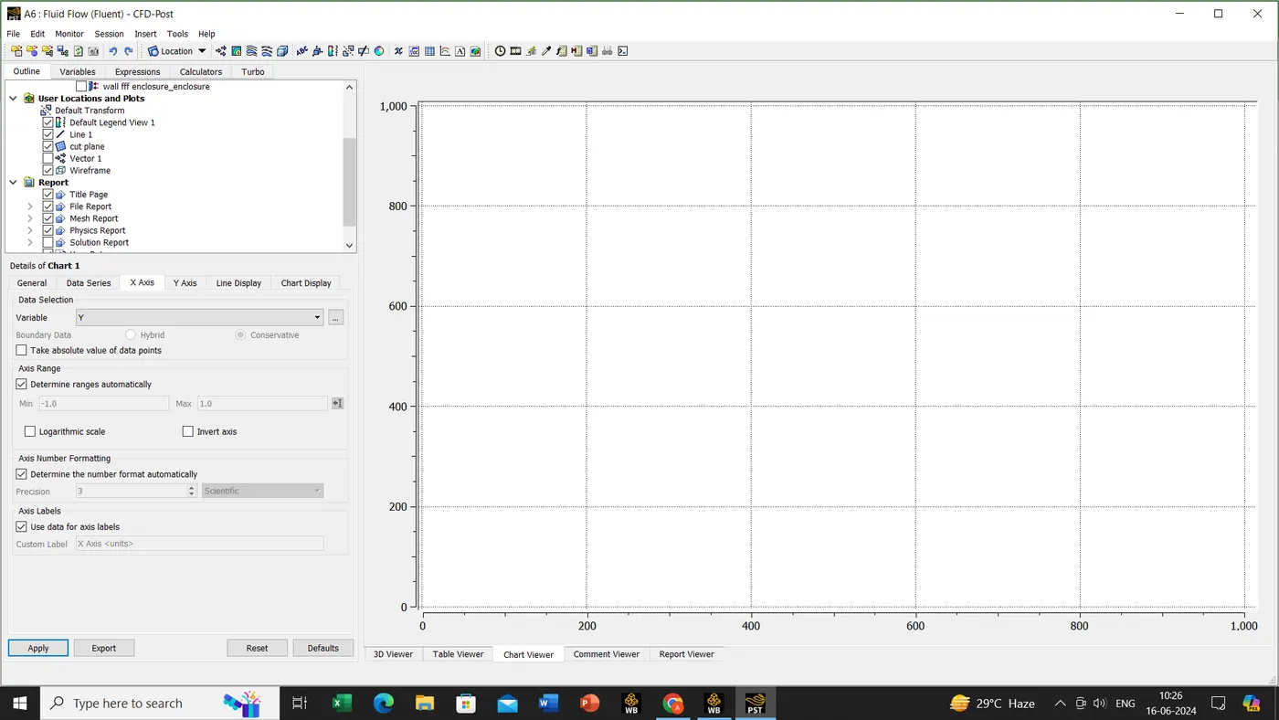
x-axis->variable ''Y''
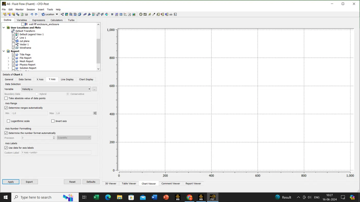
y-axis->variable ''velocity U''
Click on apply button.
Now right click on line 1 and create a duplicate line 2
click on the 3d viewer->change the co-ordinate as shown below in picture
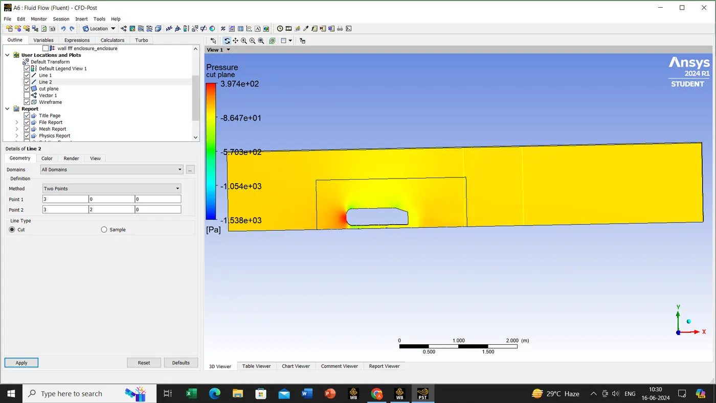
now going back to chart1 ->data series->create a new series(by clicking on the new script as shown above the red color cross mark)->location(select the line 2)-> hit the apply button on it.
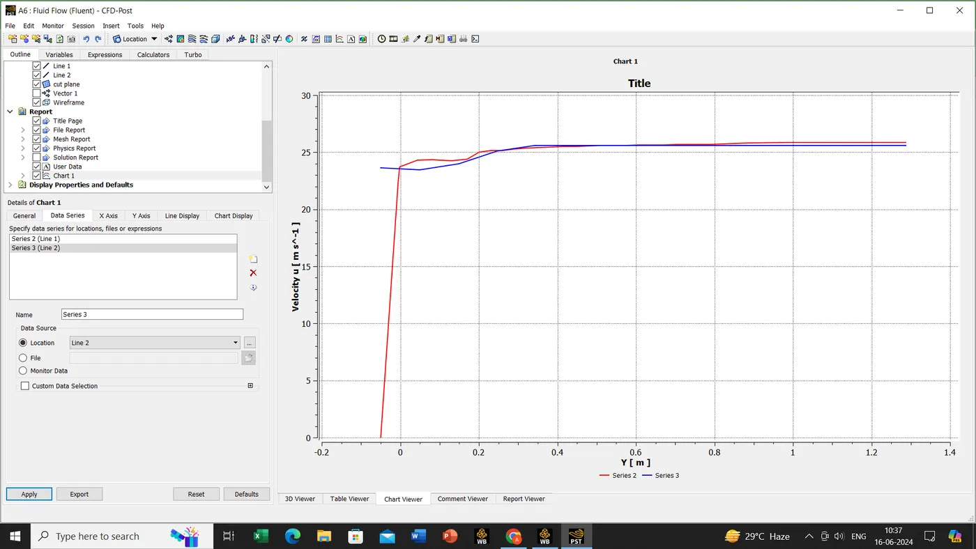
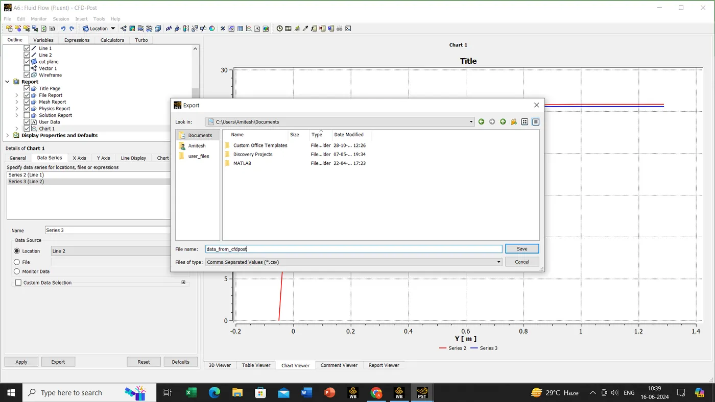
for getting the values of plane and velocity
Export->documents->assign the file name->click on save button.